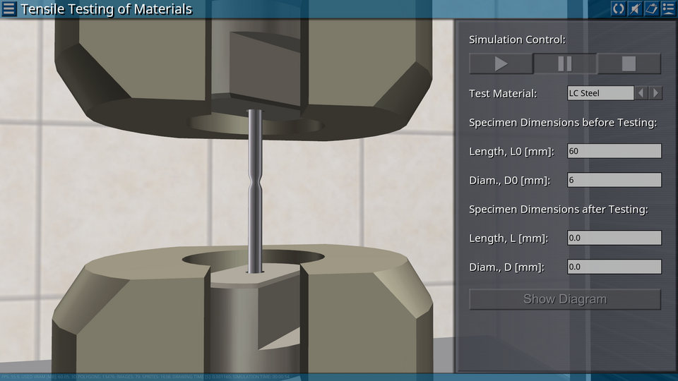
The software package «Strength of Materials» includes 12 virtual laboratory works from the strength of materials course for students for students of technical specialties.
List of virtual labs:
1. Tensile Testing of Materials 2. Compression Testing of Materials 3. Torsion Testing of Materials 4. Elastic Constants of Isotropic Materials 5. Direct Bending of the Rod 6. Oblique Bending of the Rod 7. Stresses and Displacements in a Flat Frame 8. Stresses in a Flat Great Curvature Rod 9. Stress State with Joint Bending and Torsion of a Rod 10. Experimental Verification of the Reciprocity Theorem 11. Critical Load for a Flexible Compressed Rod 12. Impact Strength of Material
Target computing device type and platform supported: IBM-compatible personal computer running Microsoft Windows.
Additionally, the package includes a web version of the virtual laboratory (HTML-5 platform), designed to be uploaded to the server of an educational organization in order to conduct remote classes with students.
The graphics component of the software uses the OpenGL 2.0 component base. The graphical user interface of the program is implemented in English.
Minimum System Requirements
Processor clock speed: at least 2 GHz
RAM: at least 4 GB
Video memory: at least 512 MB
Screen resolution: at least 1024x768x32
OpenGL version 2.0 support
DirectX version 9.0.c support (for Windows)
Standard keyboard and computer mouse with scroll wheel (for PC)
Audio playback devices (audio speakers or headphones)
To work with the web version of the virtual laboratory, you must use a web browser that supports WebGL 3D graphics, for example, Google Chrome, Microsoft Edge, Opera, Mozilla Firefox. The HTML components of the web version must be uploaded to a physical server. If you need to use a local server, it is recommended to use the XAMPP (Apache) assembly.
Types of Licensing
The Virtual Lab is supplied only for educational organizations with installation on an unlimited number of places (corporate license).
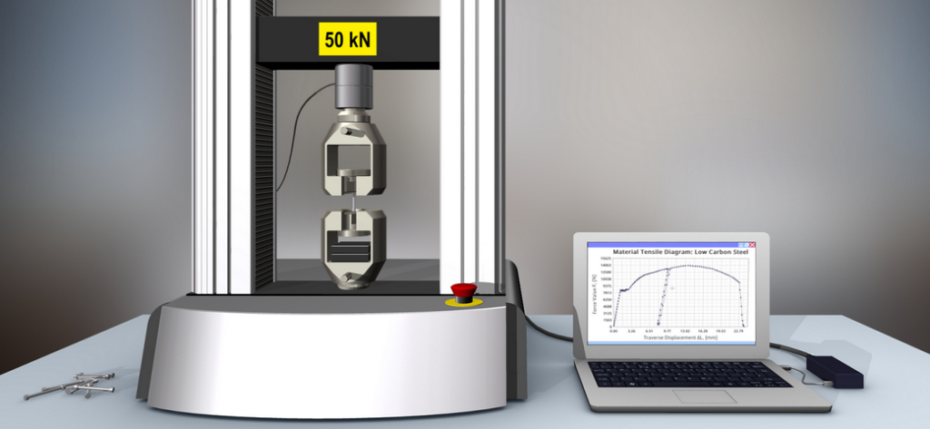
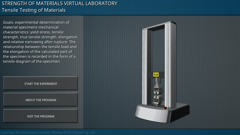
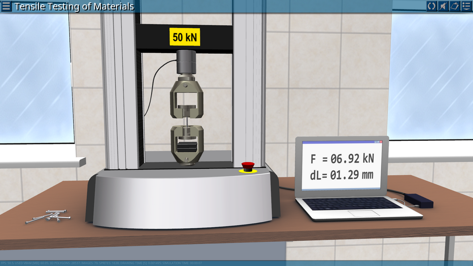
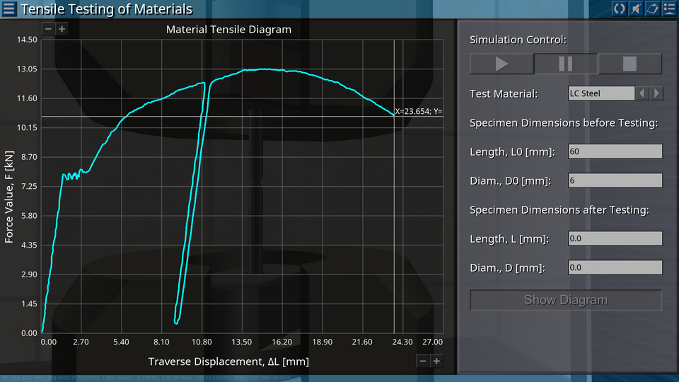
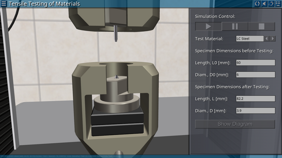
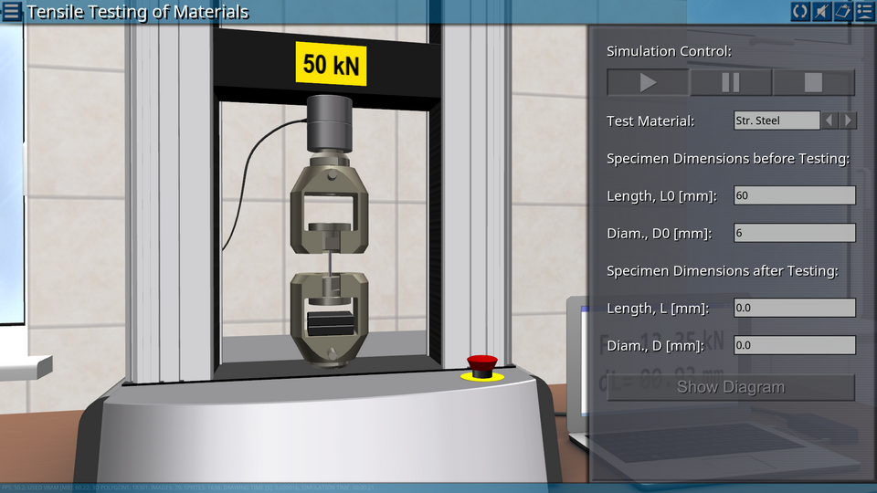
1. Tensile Testing of Materials
OBJECTIVE: Determination of the mechanical characteristics of the material under tension. SUMMARY: Tensile tests of material specimens are carried out for the purpose of experimental determination of mechanical characteristics: yield stress, tensile strength, true tensile strength, elongation and relative narrowing after rupture. In the tensile test, a specimen of a certain shape and size made of test material is firmly fixed by its ends (heads) in the grippers of the testing machine and subjected to continuous gradual deformation prior to failure. In this case, the relationship between the tensile load and the elongation of the calculated part of the specimen is recorded in the form of a tensile diagram of the specimen.
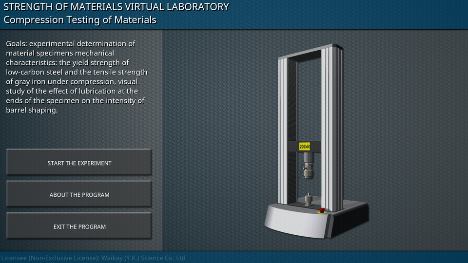
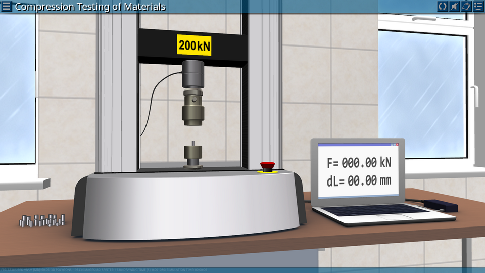
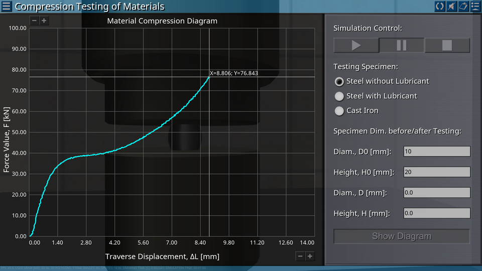
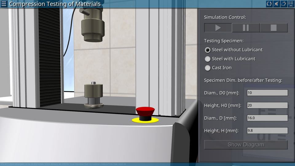
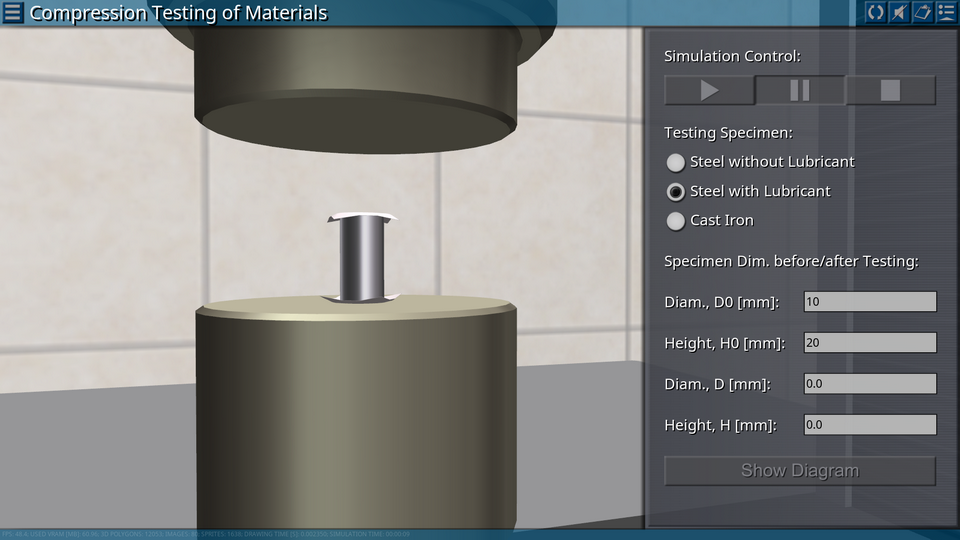
OBJECTIVE: Determination of the mechanical characteristics of the material during compression and visual study of the effect of lubrication at the ends of the specimen on the intensity of barrel shaping. SUMMARY: The compression test of the material specimens is carried out for the purpose of experimental determination of the mechanical characteristics: the yield strength of low-carbon steel and the tensile strength of gray iron under compression. In the compression test, a specimen of the standard shape and dimensions made of test material is placed on the working surface of the testing machine, and subjected to continuous, smooth deformation to a specified value of deformation or to failure. The relationship between the compressive force and the shortening of the specimen height in the form of a specimen compression diagram is recorded.
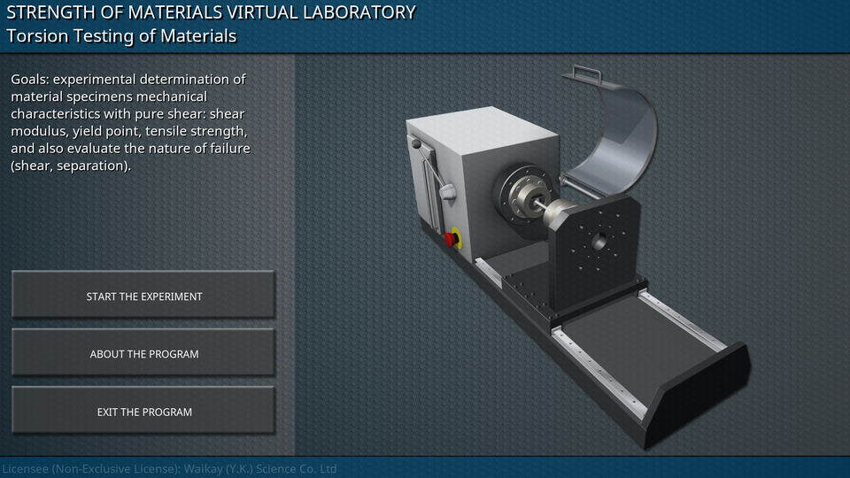
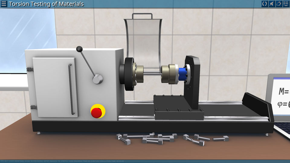
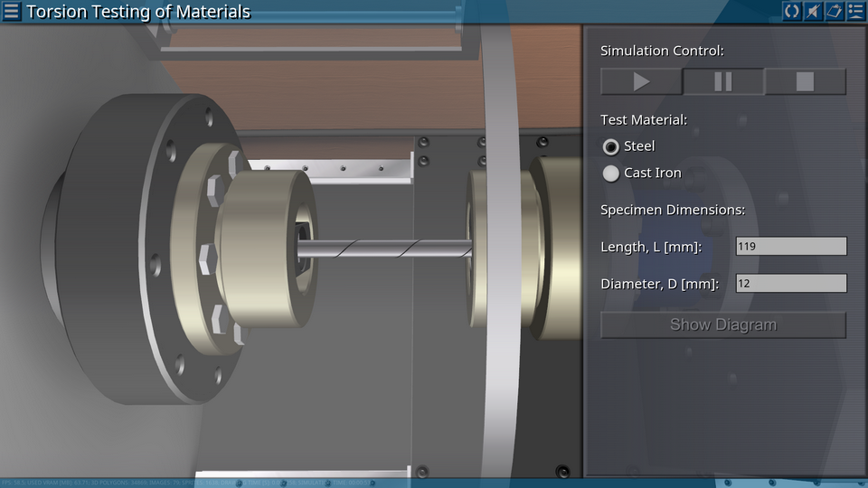
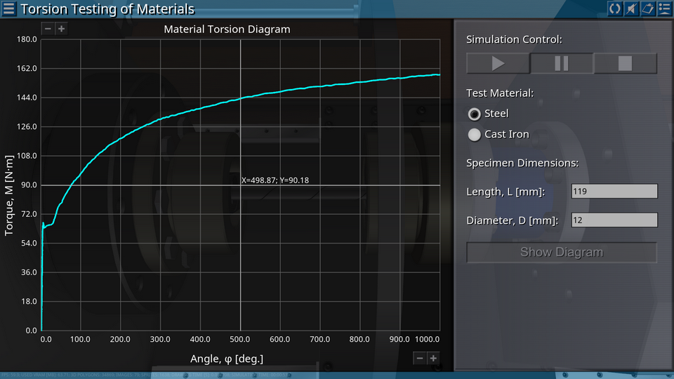
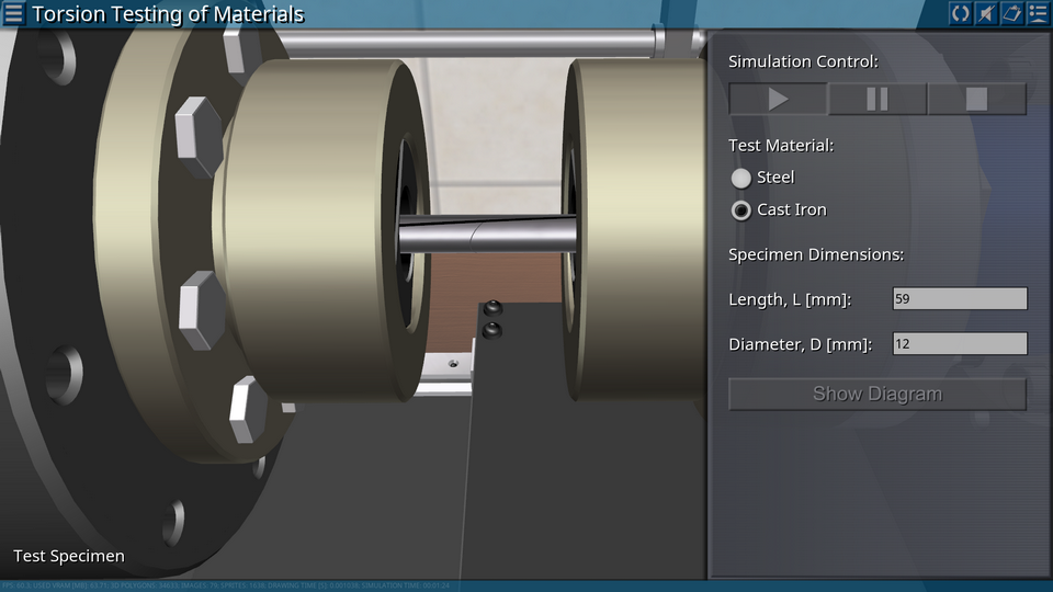
OBJECTIVE: Experimental determination of the mechanical characteristics of the material during torsion. SUMMARY: Torsion testing of material specimens is carried out for the purpose of experimental determination of mechanical characteristics with pure shear: shear modulus, yield point, tensile strength, and also evaluate the nature of failure (shear, separation). In the torsion test, the specimen made of test material is firmly fixed by the heads in the grippers of the testing machine and subjected to continuous gradual deformation prior to failure. When torsion testing, the following basic conditions must be observed: qualitative centering of the specimen in the grippers of the testing machine, smooth loading and unloading, and lack of longitudinal force.
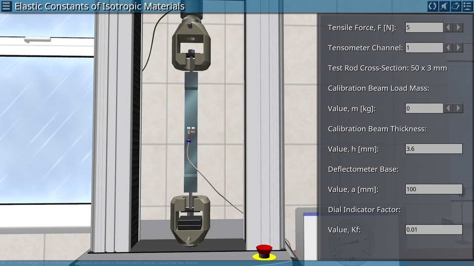
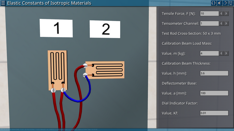
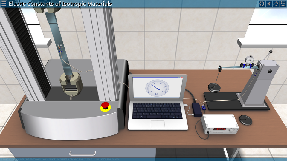
OBJECTIVE: Experimental determination of the elastic modulus of the first kind and Poisson’s ratio for steel. SUMMARY: As a testing object, a rod of rectangular cross-section, fixed in the grippers of the testing machine and loaded with longitudinal force, is used. Two strain gage are glued on the specimen before the tests: one in the longitudinal direction, the other in the transverse one. During the test, the deformation meter is calibrated. As a result of loading the specimen, longitudinal and transverse deformations are measured, the values of which determine the modulus of elasticity and the Poisson’s ratio of the material under investigation.
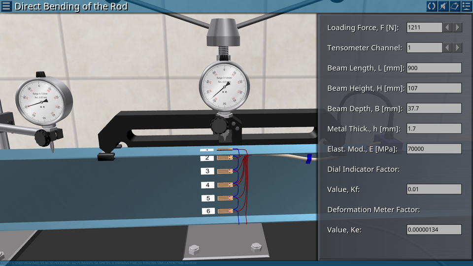
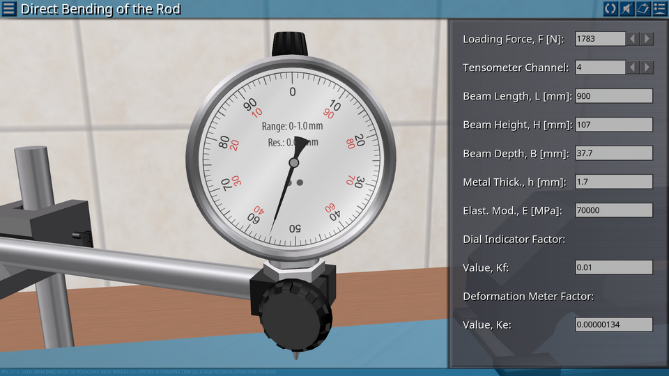
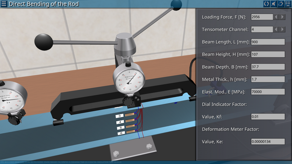
OBJECTIVE: Experimental and theoretical determination of stresses and displacements in a beam of an I-section under direct bending. Experimental verification of the law of distribution of normal stresses under pure bending. SUMMARY: The main element of the laboratory installation is: an I-sectional beam made of aluminum alloy, mounted on two supports. The beam is loaded through a yoke, which is also an elastic element of the force meter. The middle part of the beam (between the supports of the yoke) is in the conditions of pure bending. In the middle section of the beam, seven foil-type strain gauges are glued. The strain gages are installed in the direction of the longitudinal axis of the beam and allow the deformation to be measured at the corresponding points.
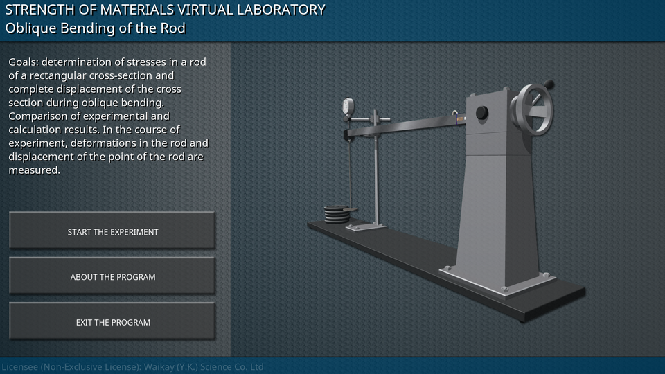
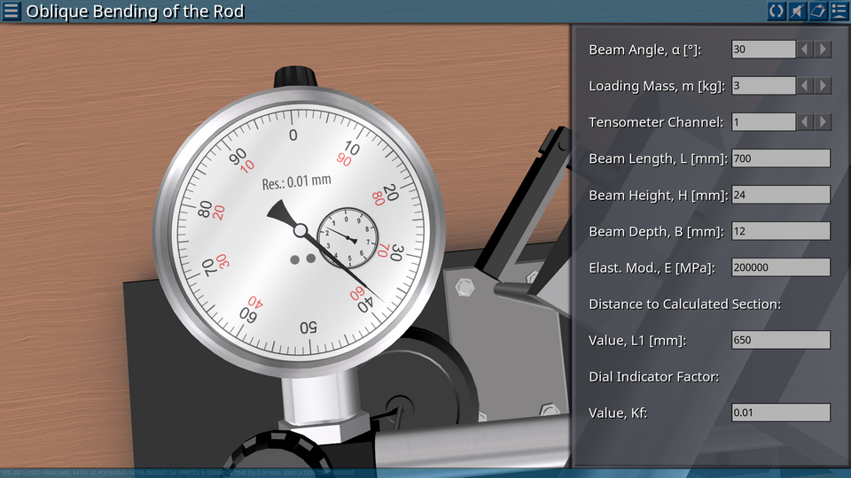
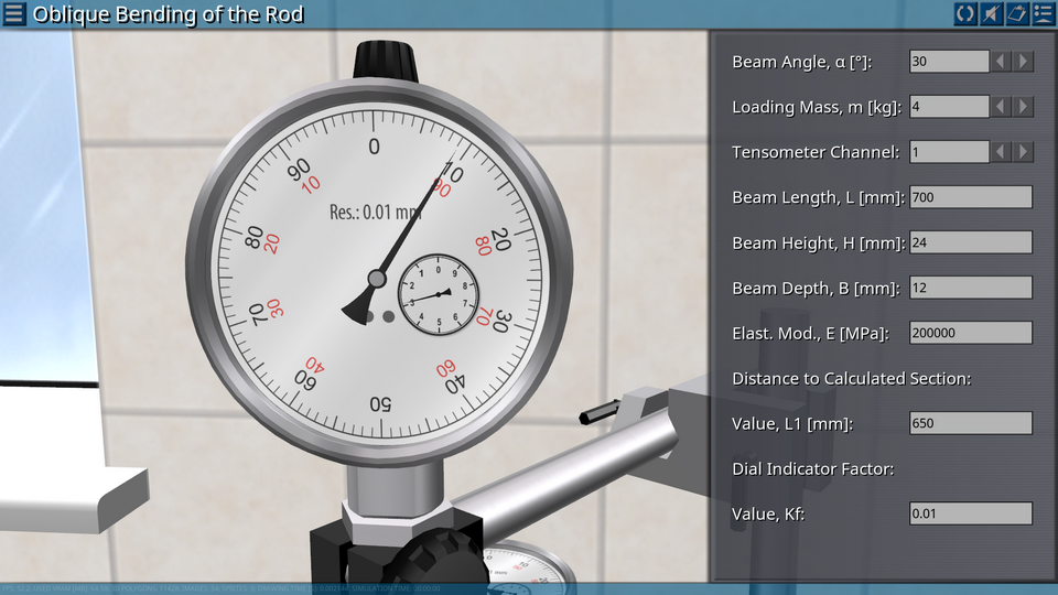
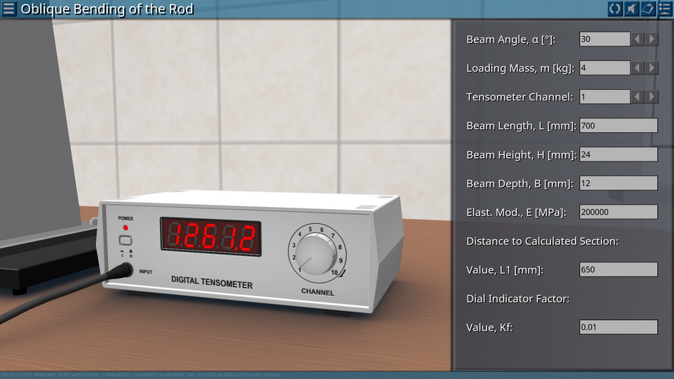
OBJECTIVE: Determination of stresses in a rod of a rectangular cross-section and complete displacement of the cross section during oblique bending. Comparison of experimental and calculation results. SUMMARY: The main element of the laboratory installation is a cantilevered rod, loaded with a vertical force. The design of the support allows the rod to rotate relative to its longitudinal axis and secure it in the established position. The position of the rod is controlled by means of an angular scale applied to the movable part of the rod support. At the free end of the rod, a suspension is mounted on the cylindrical hinge, on which the weights are loaded when the rod is loaded. The design of the suspension allows you to apply force only in the vertical direction. In the course of experiment, deformations in the rod and displacement of the point of the rod are measured.
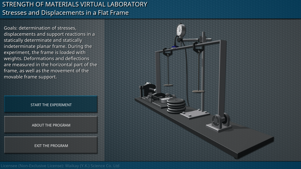
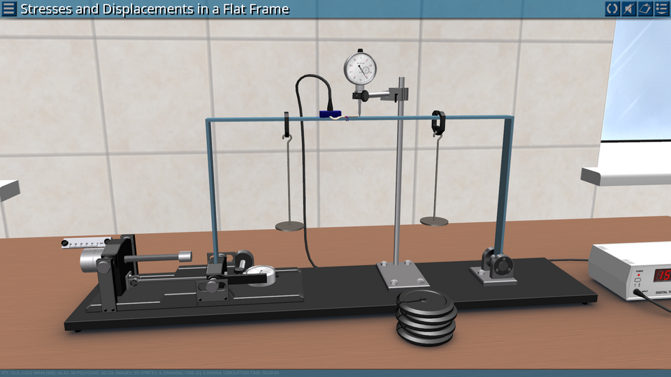
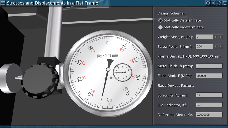
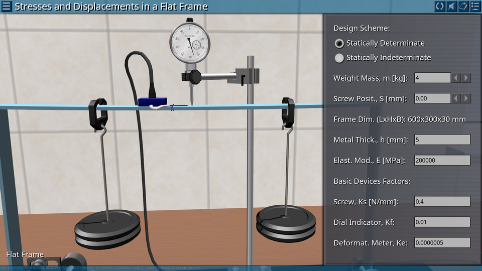
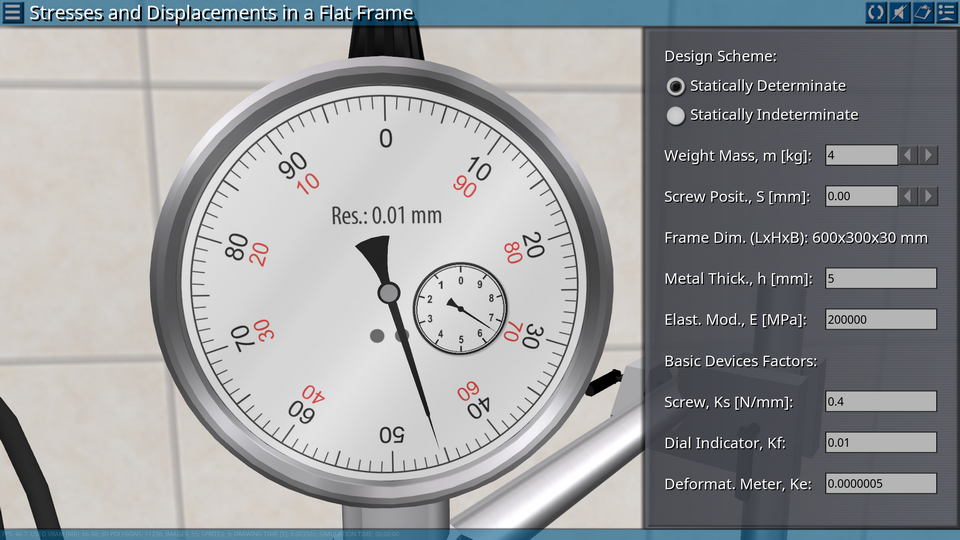
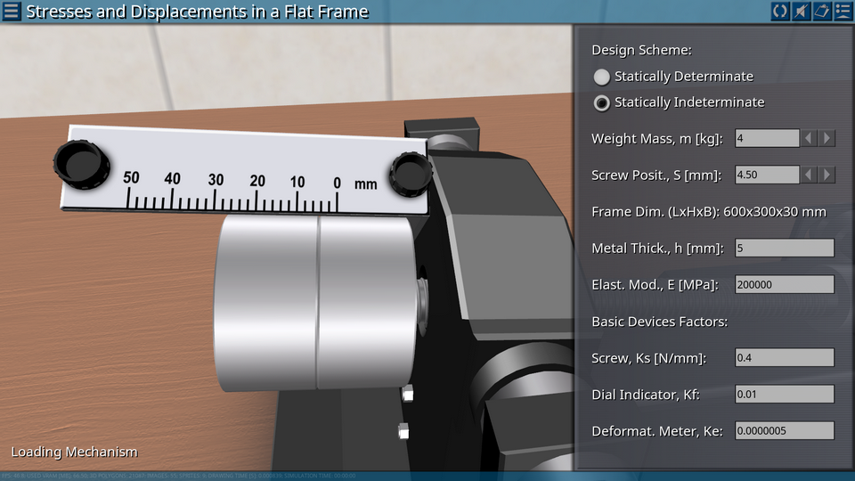
OBJECTIVE: Determination of stresses, displacements and support reactions in a statically determinate and statically indeterminate planar frame. SUMMARY: The main element of the laboratory installation is a flat frame consisting of three rigidly fixed rods of rectangular cross-section. The frame is mounted on two hinged supports, which attach three bonds to the frame. The construction of one of the supports makes it possible to impose an additional horizontal bond, i.e. allows the transition to a statically indeterminate flat frame. During the experiment, the frame is loaded with weights. Deformations and deflections are measured in the horizontal part of the frame, as well as the movement of the movable frame support.
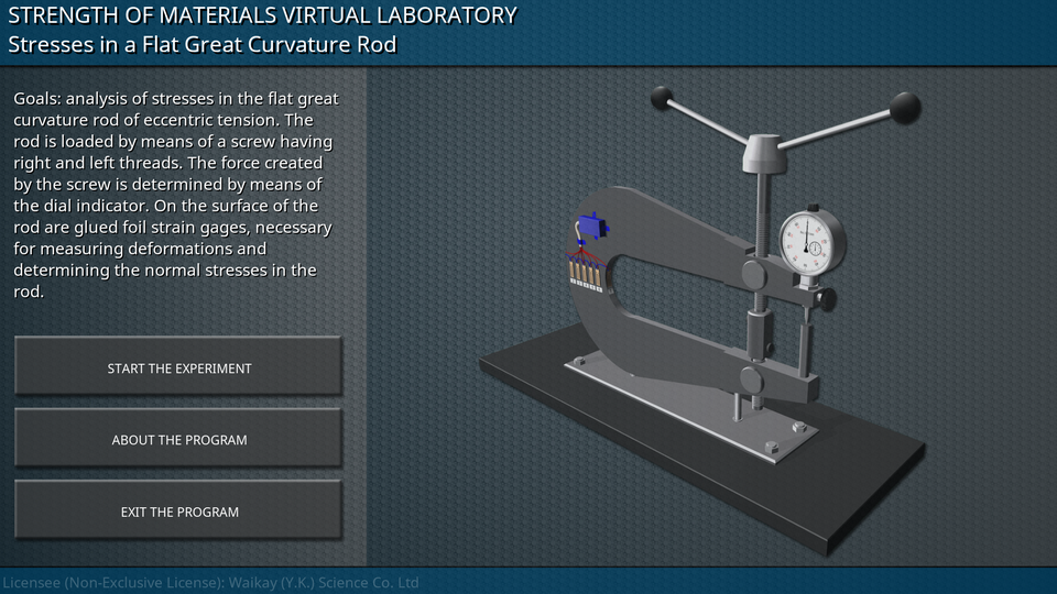
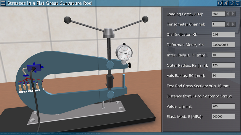
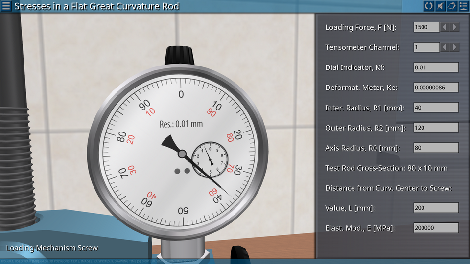
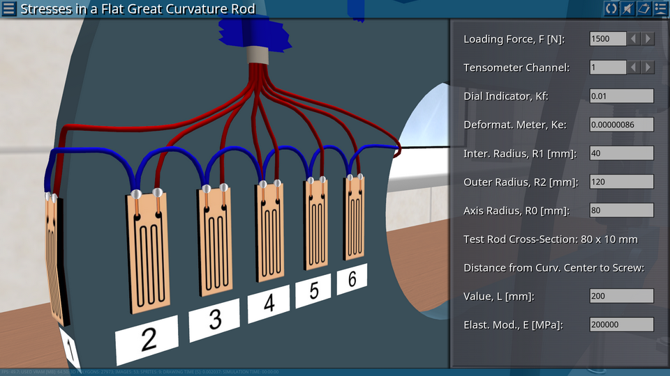
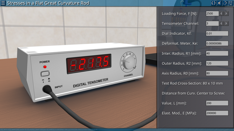
OBJECTIVE: Analysis of stresses in the flat great curvature rod of eccentric tension. SUMMARY: The main element of the laboratory installation is a flat great curvature rod of a rectangular cross-section. The rod is fixedly fixed to the baseplate of the laboratory stand. The rod is loaded by means of a screw having right and left threads. Rotating the screw in one or another direction carries out eccentric stretching or compression of the curved rod. The force created by the screw is determined by means of the indicator of the hour type and the calibration table. On the surface of the rod are glued foil strain gages, necessary for measuring deformations and determining the normal stresses in the rod.
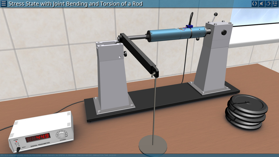
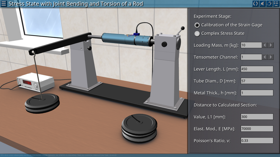
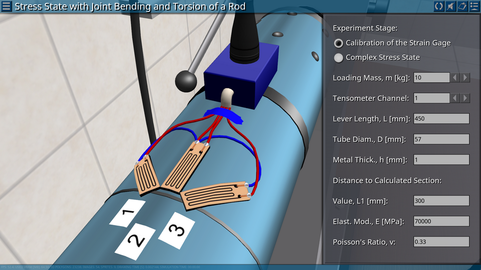
9. Stress State with Joint Bending and Torsion of a Rod
OBJECTIVE: Comparison of the results of theoretical calculation and experimental study of the stressed state of points of a curved and twisted rod. SUMMARY: The main element of the laboratory installation is a tubular rod, loaded with bending and twisting moments. In the cross-section of the rod three strain gauges are glued to measure deformation. Deformation is measured by means of an electronic deformation meter. For the calibration of the scale of the electronic deformation meter in the design of the installation, it is possible to mount a hinged support on the free edge of the rod, in this case the rod is loaded only by the torque.
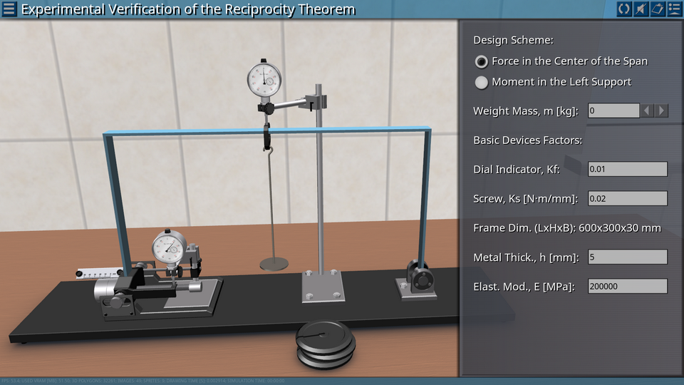
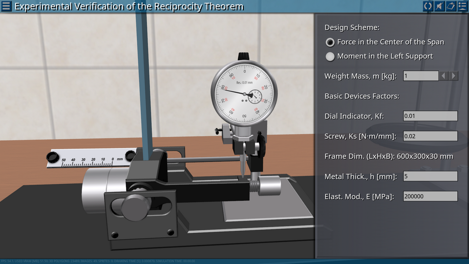
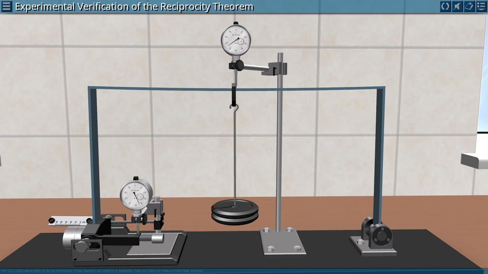
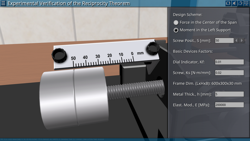
10. Experimental Verification of the Reciprocity Theorem
OBJECTIVE: Experimental verification of the validity of the reciprocity theorem on the example of displacements in a flat frame under different loading conditions. SUMMARY: The main element of the laboratory installation is a flat frame consisting of three rigidly connected rods of a rectangular cross-section. The frame is mounted on two hinged supports. The construction of one of the supports makes it possible to apply a load in the form of a concentrated moment to the frame. This is achieved by shifting the loads fixed on the screw while rotating it. The frame is loaded by weights. Measures the deflection in the horizontal part of the frame, as well as the movement of the movable frame support.
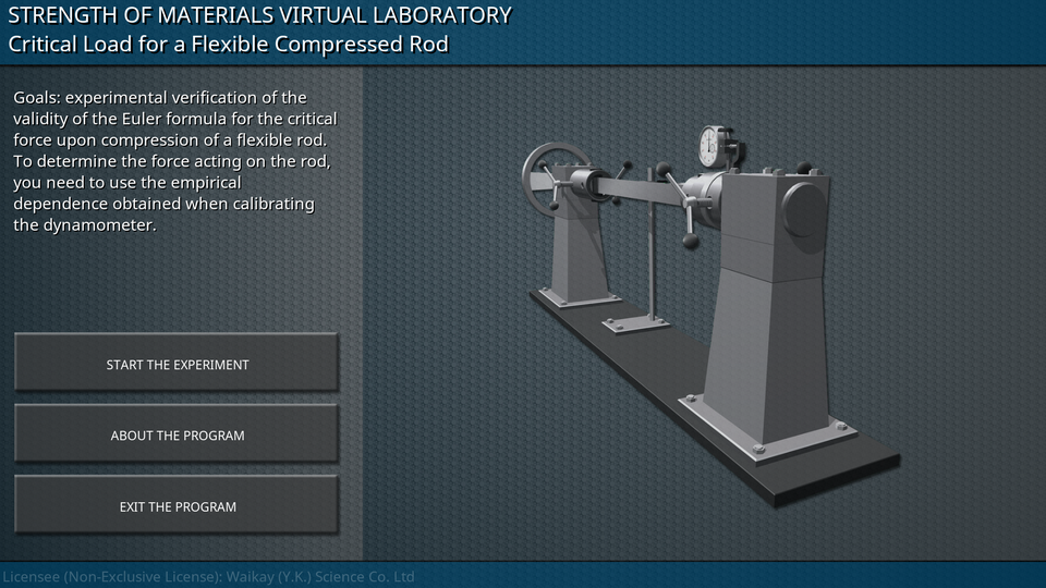
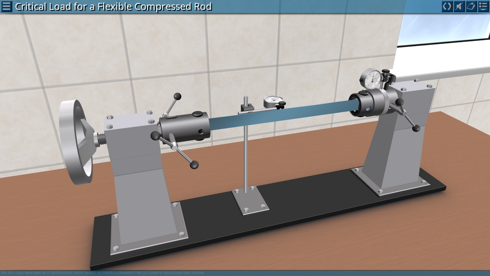
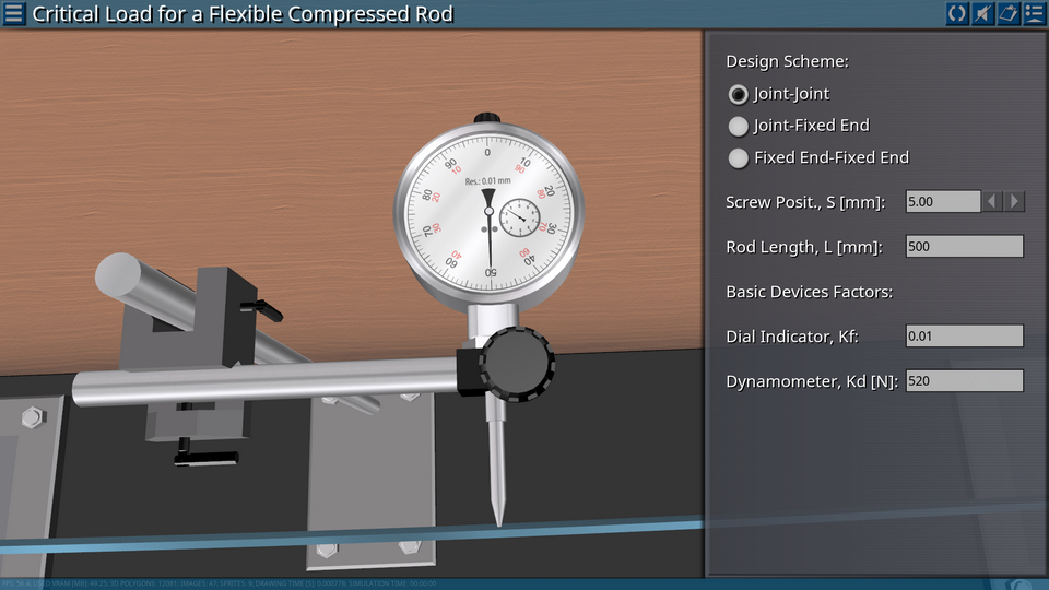
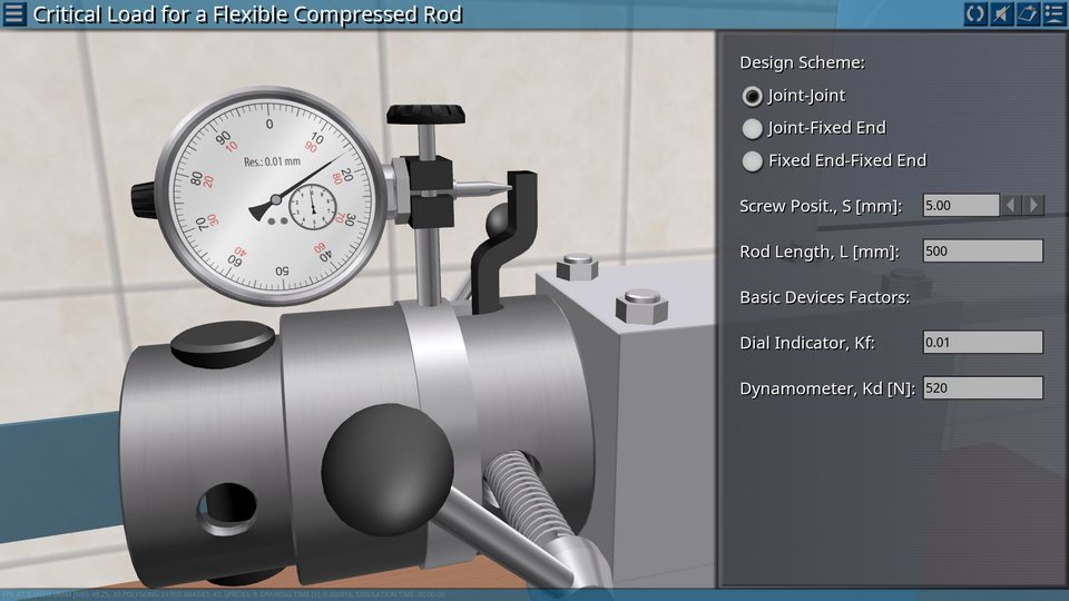
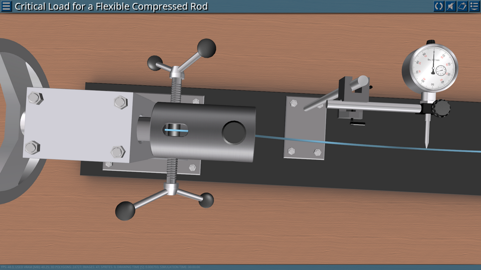
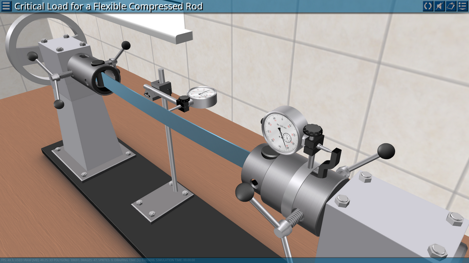
OBJECTIVE: Experimental verification of the validity of the Euler formula for the critical force upon compression of a flexible rod. SUMMARY: The main element of the laboratory installation is a rod of a rectangular cross-section. The rod is installed in the right and left supports, the design of which allows the hinged or rigid fastening of the rod ends in the plane of least rigidity. The right support is connected to a dynamometer using a calibrated hour indicator, the left one to a screw type loading device. In the middle section of the rod is installed a deflectometer (indicator of the watch type on the stand). To determine the force acting on the rod, you need to use the empirical dependence obtained when calibrating the dynamometer.
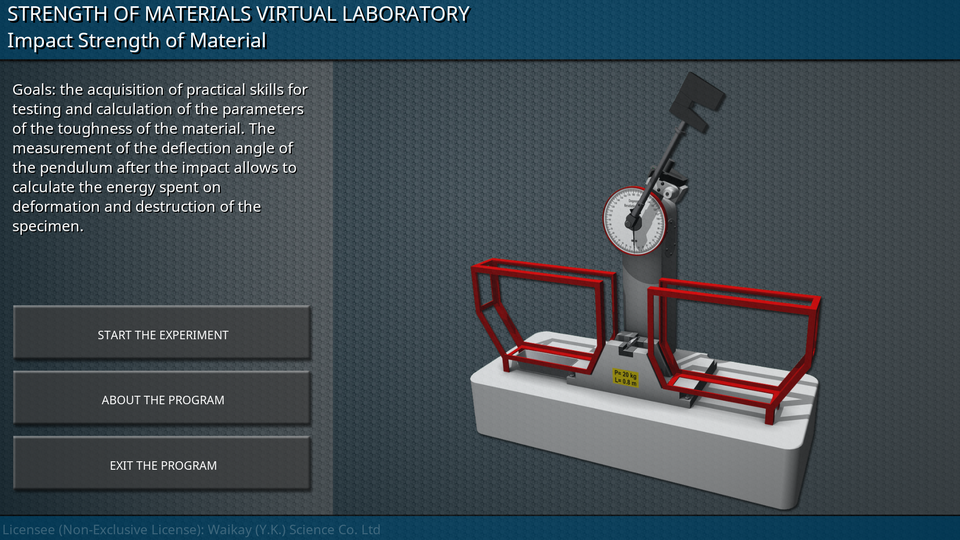
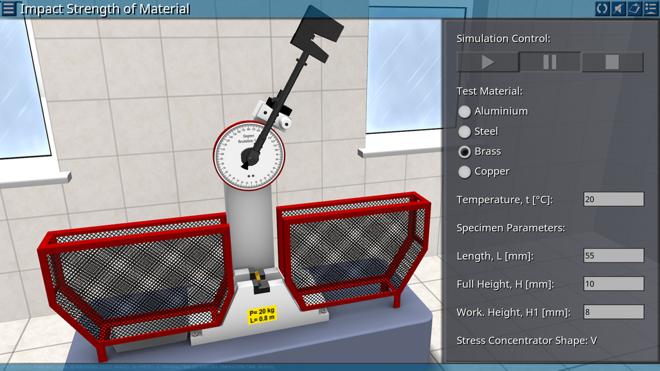
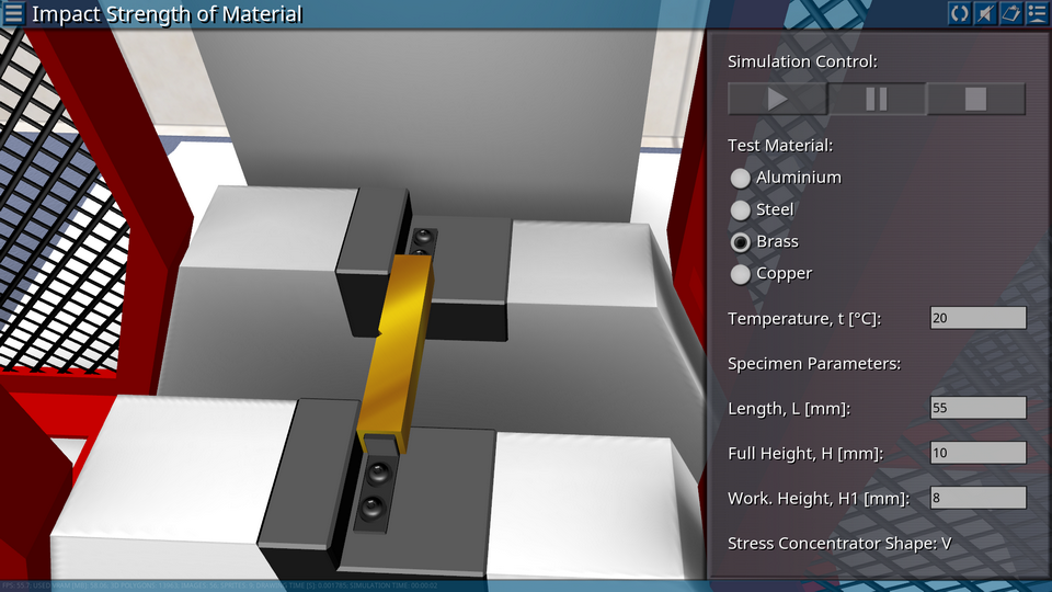
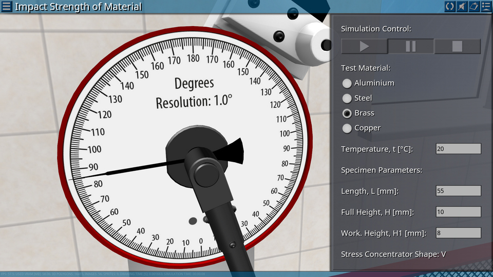
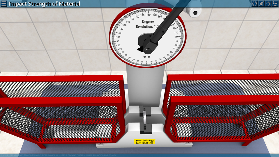
OBJECTIVE: The acquisition of practical skills for testing and calculation of the parameters of the toughness of the material. SUMMARY: For the test, a pendulum coper is used, the design of which provides a shock effect on the specimen and the measurement of the deflection angle of the pendulum after the impact, which allows to calculate the energy spent on deformation and destruction of the specimen. Energy is defined as the difference between the initial supply of potential energy of the pendulum and the energy remaining at the pendulum after the destruction of the specimen.