Software laboratory complex «Theoretical Hydromechanics» for the simulation of laboratory work on the main sections of the course of Theoretical Hydromechanics for technical specialties.
List of virtual labs:
1. The Study of Pascal’s Law 2. The Relative Rest of the Fluid During Rotational Motion 3. Experimental Determination of the Terms of Bernoulli’s Equation 4. The Construction of Bernoulli’s Diagram 5. The Study of Hydraulic Resistance of Pressure Pipe 6. The Study of the Laminar and Turbulent Flow of Fluid 7. The Study of Fluid Flow through Small Holes in a Thin Wall and Nozzles 8. The Study of the Direct Water Hammer in Pressure Pipe 9. The Study of Filtration in Sandy Soil at Darcy Device 10. The Parametric Tests of Centrifugal Pump 11. The Cavitation Tests of Centrifugal Pump 12. The Study of Centrifugal Fan Characteristics 13. The Determination of Velocity in the Cross Section of a Round Pipe
Target computing device type and platform supported: IBM-compatible personal computer running Microsoft Windows.
The graphics component of the software uses the Microsoft DirectX 9.0.c component base. The graphical user interface of the program is implemented in English.
Minimum System Requirements
Processor clock speed: at least 1.5 GHz
RAM: at least 2 GB
Video memory: at least 256 MB
Screen resolution: at least 1024x768x32
DirectX version 9.0.c support
Standard keyboard and computer mouse with scroll wheel (for PC)
Audio playback devices (audio speakers or headphones)
Types of Licensing
The Virtual Lab is supplied only for educational organizations with installation on an unlimited number of places (corporate license).
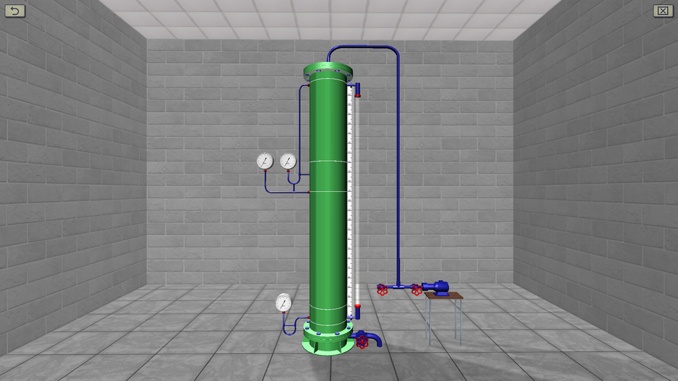
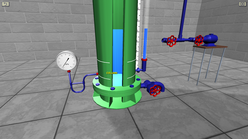
1. The Study of Pascal's Law
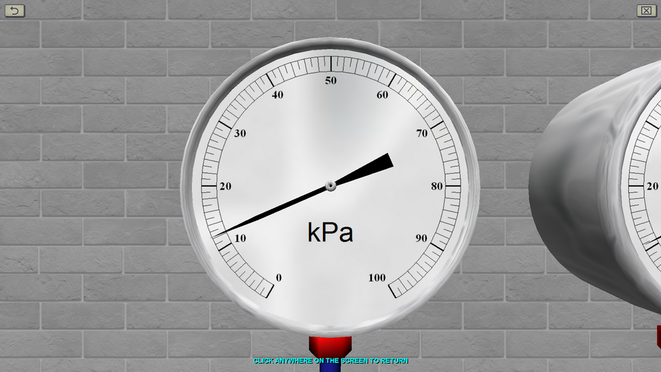
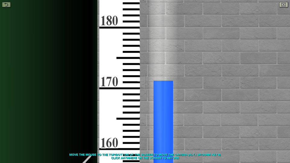
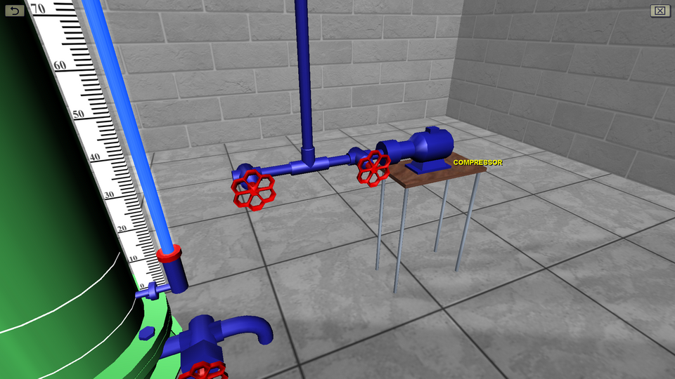
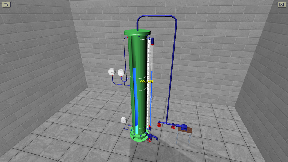
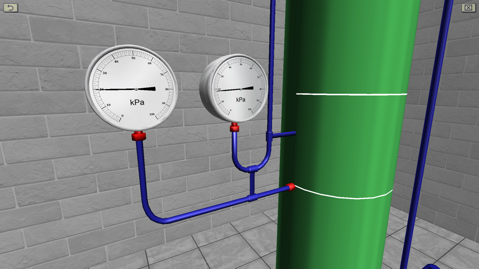
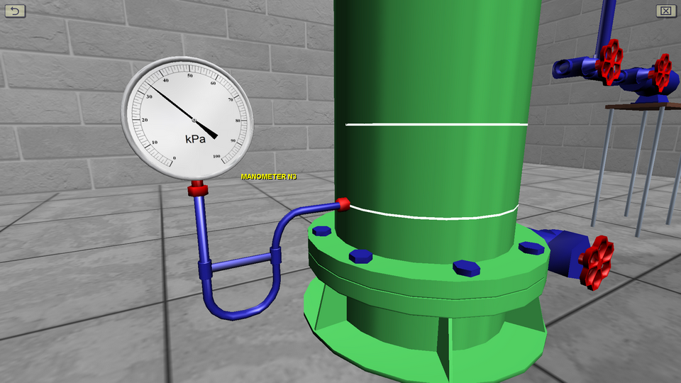
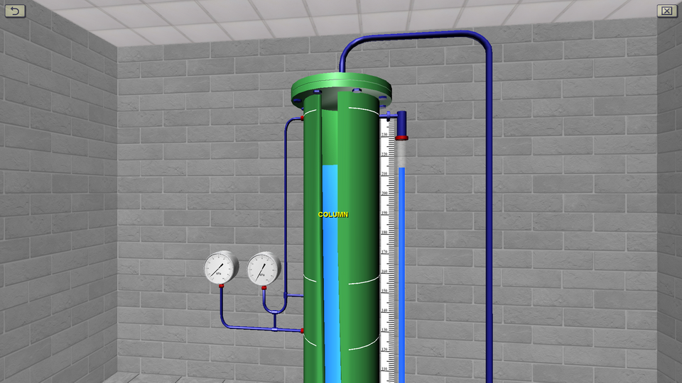
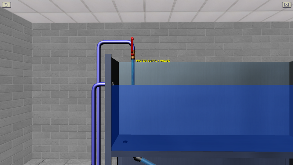
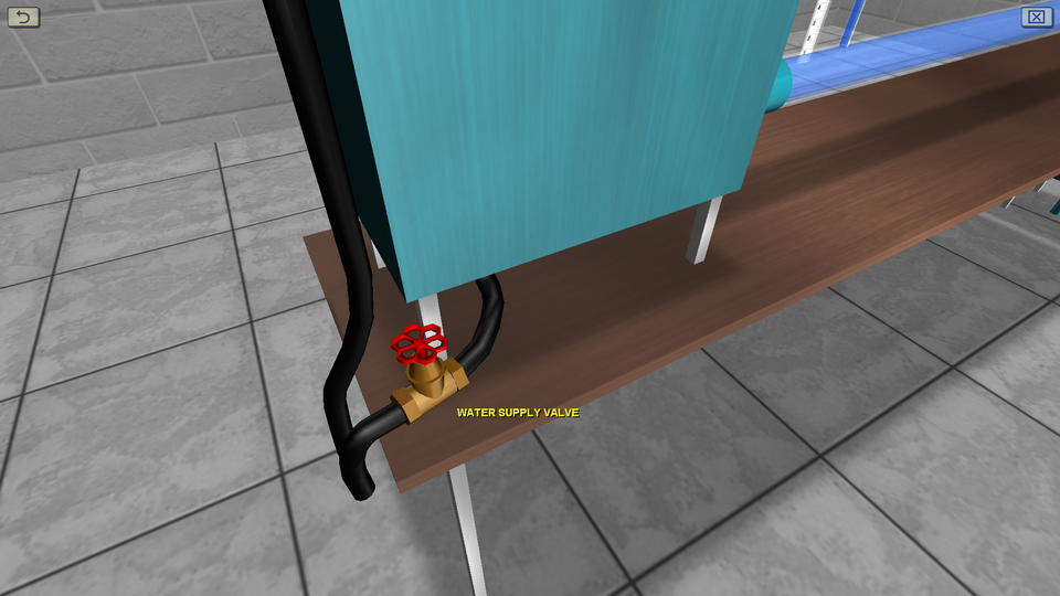
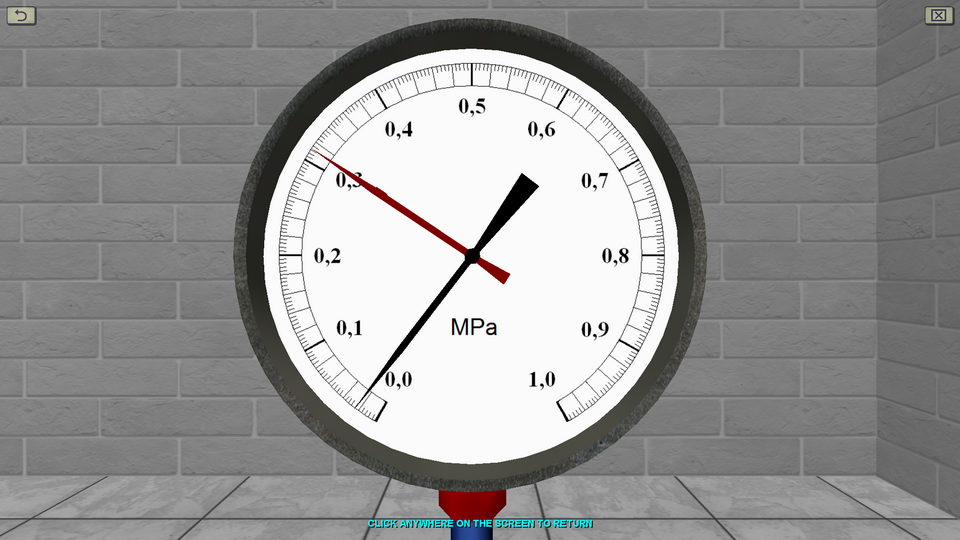
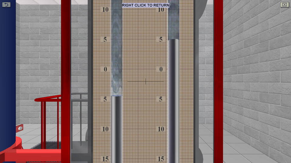
OBJECTIVE: The measurement with the help of spring pressure gauges of hydrostatic pressure at three points of the column, deepened at different values of height the level of the liquid, which is absolutely at rest under the action of gravity; confirmation based on the experimental data of the basic hydrostatic equation and Pascal’s law; plotting the gauge pressure graph versus depth. SUMMARY: The laboratory stand is presented in the form of a vertical column into which water is supplied from the bottom up. Compressed air can be forced into the upper part of the column using a compressor. At three points of the column are connected spring pressure gauges, measuring the hydrostatic pressure of water. Laboratory work clearly demonstrates the basic principles of theoretical hydromechanics.view publisher siteoriginal site
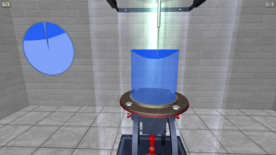
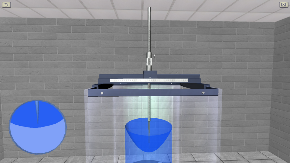
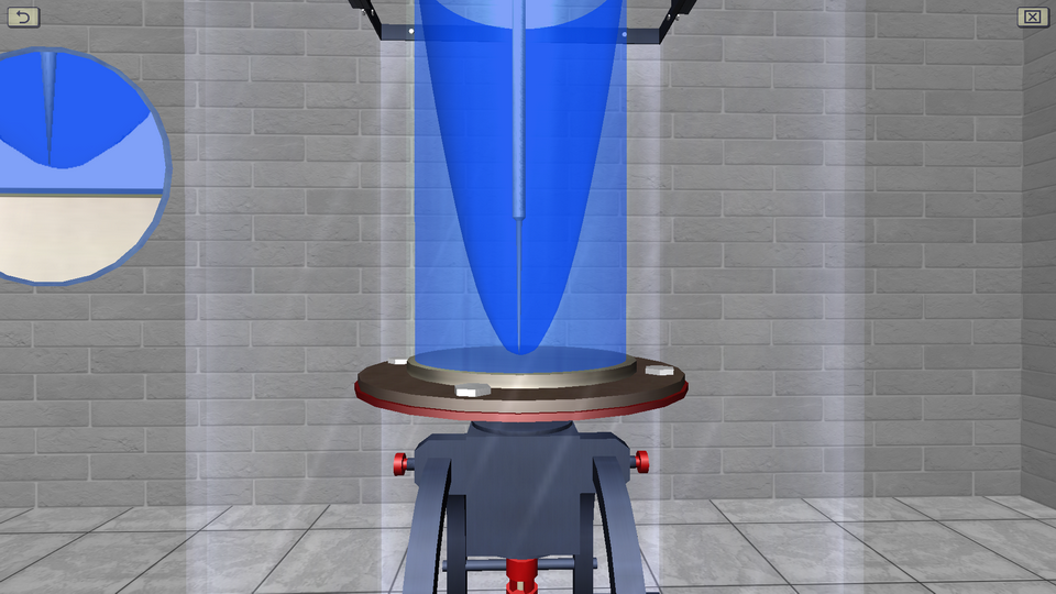
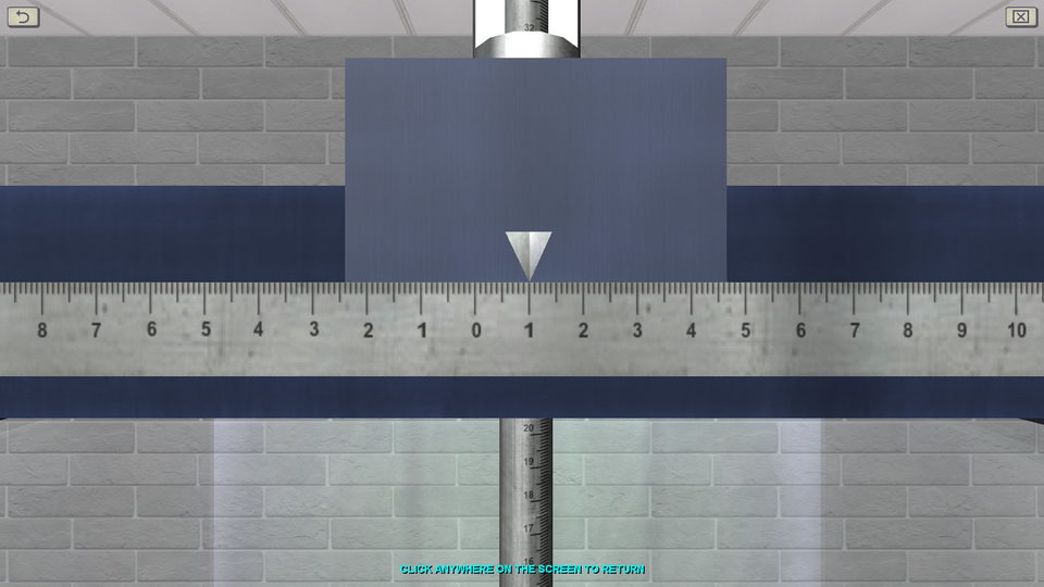
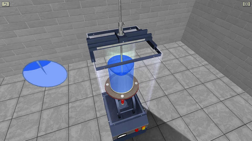
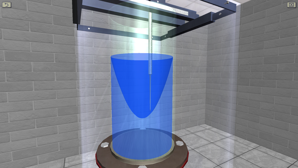
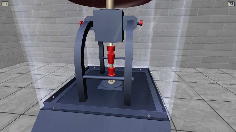
2. The Relative Rest of the Fluid During Rotational Motion
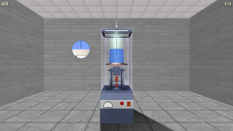
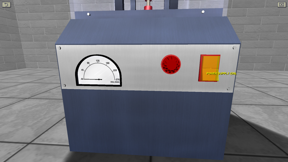
OBJECTIVE: The observation the process of establishing the equilibrium of water in an open cylinder, rotating at a constant angular velocity around the vertical axis; measurement of the coordinates of five points of the free surface of the liquid, located at different distances from the axis of rotation; measuring the height of the paraboloid of rotation and comparing it with the theoretical (with determining the relative deviation). SUMMARY: The laboratory stand consists of a rotating platform on which a water tank is installed. The rotation of the platform is carried out with the help of an electric motor, the rotational speed of which is regulated during operation. Measurement of the marks of the free surface of the liquid is carried out using a measuring needle.
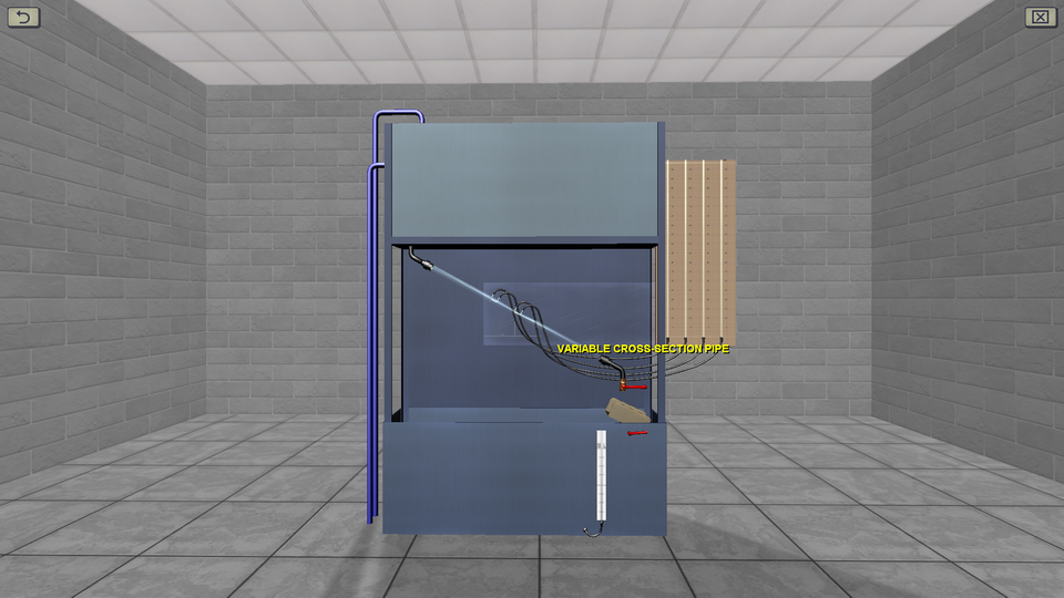
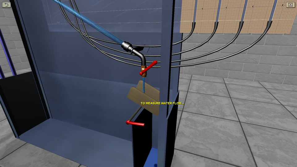
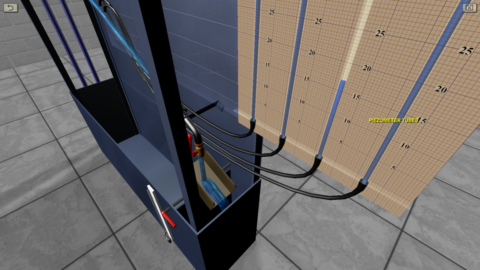
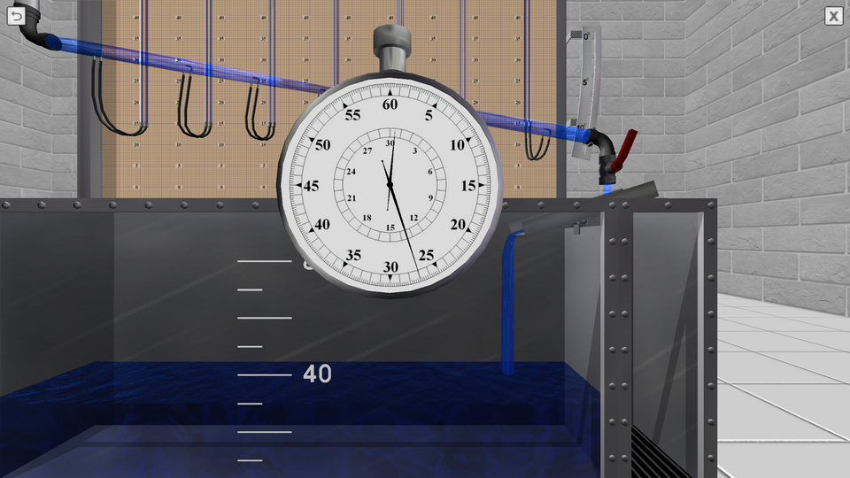
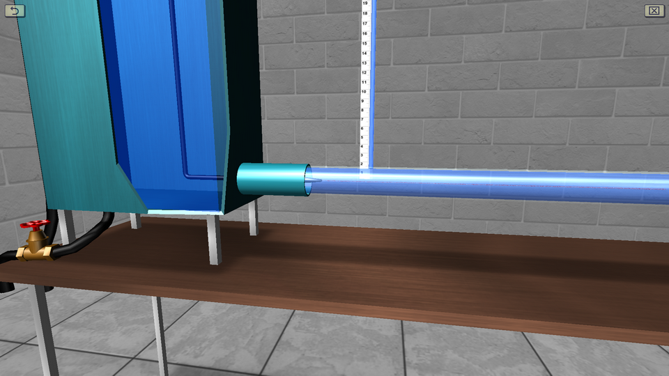
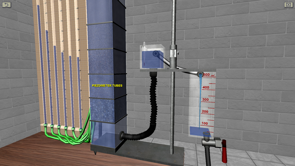
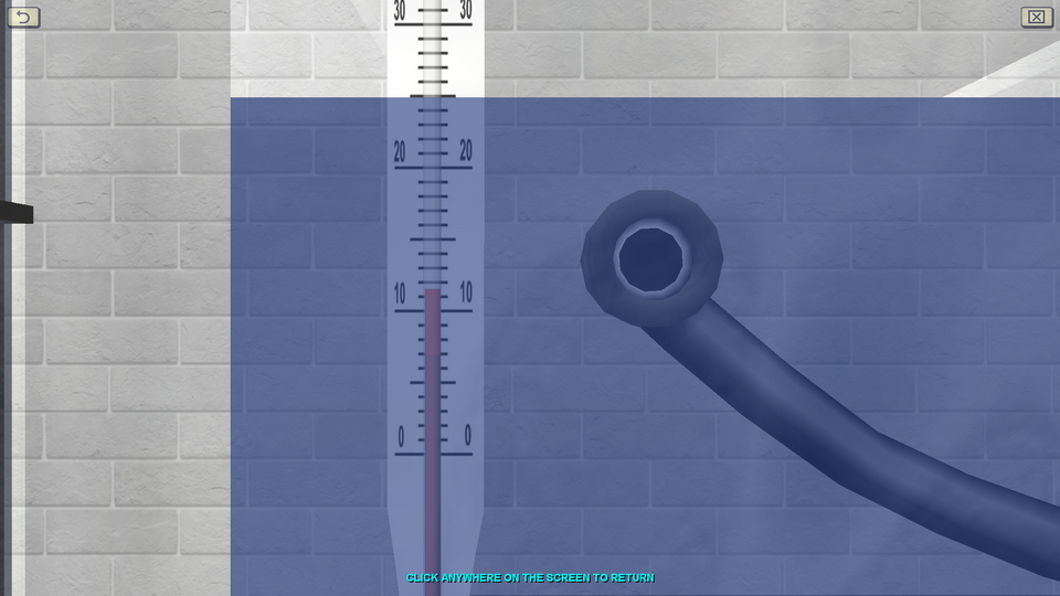
3. Experimental Determination of the Terms of Bernoulli's Equation
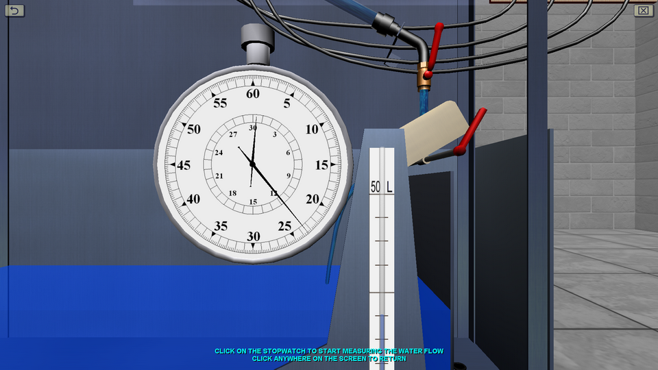
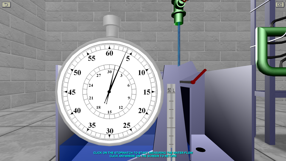
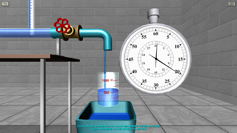
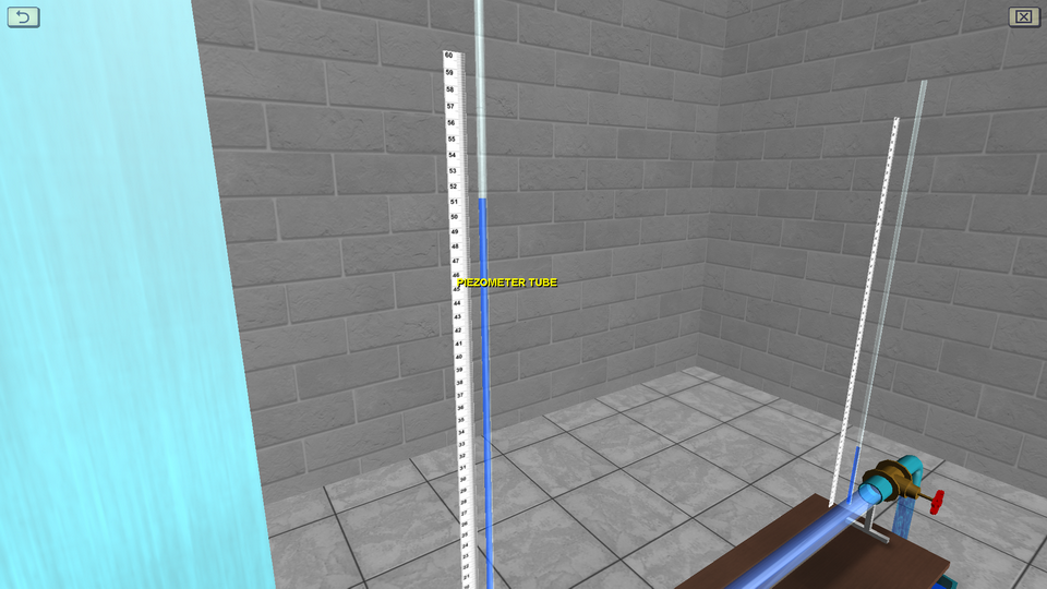
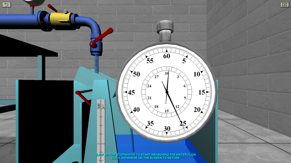
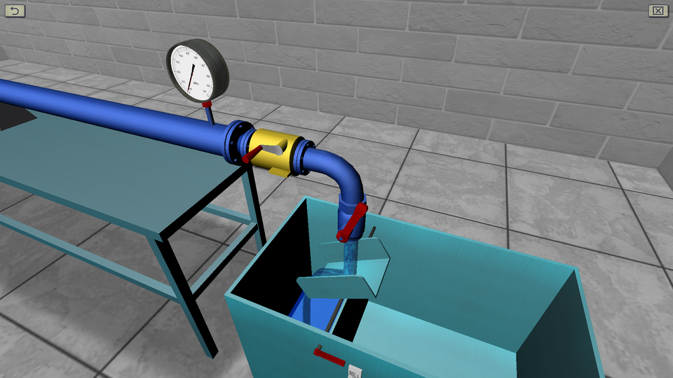
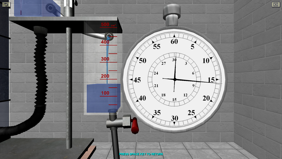
OBJECTIVE: The experimentally determination the terms of the D. Bernoulli’s equation for two cross-sections of a glass tube, as well as the loss of total pressure between sections; calculating the average flow rates and the corresponding velocity heads for the indicated living sections of the fluid flow; plotting, on the scale of experimental data, a piezometric line and a full pressure line. SUMMARY: The study of Bernoulli’s law plays an important role in applied and theoretical hydromechanics. The laboratory stand includes a pressure tank, a glass tube of variable cross section, a flow meter tank and a system of measuring piezometers connected by flexible hoses to a glass tube. Water flow in the system is measured using a stopwatch.
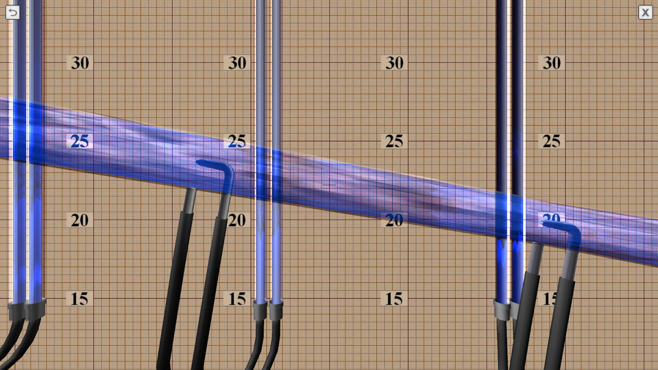
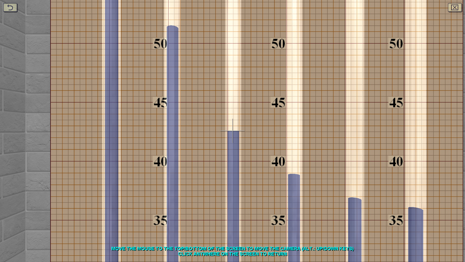
4. The Construction of Bernoulli's Diagram
OBJECTIVE: The observation the transition of specific energy in a fluid flow from potential to kinetic energy and back in accordance with D. Bernoulli’s equation on a discharge pipe of variable cross section using piezometers, as well as construction a piezometric and pressure line for the water flow by experimental data. SUMMARY: The hydraulic system includes a pressure tank, a glass tube of variable cross section (expanding/tapering in the middle), a system of measuring piezometers and a flow meter tank. The angle of the glass tube is adjustable during operation. Water flow in the system is measured using a stopwatch.
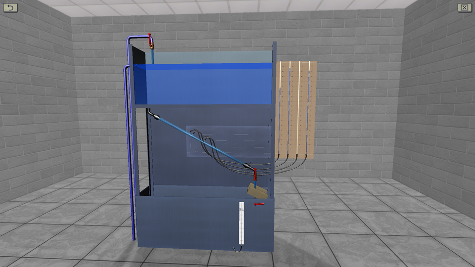
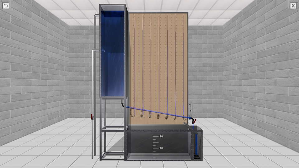
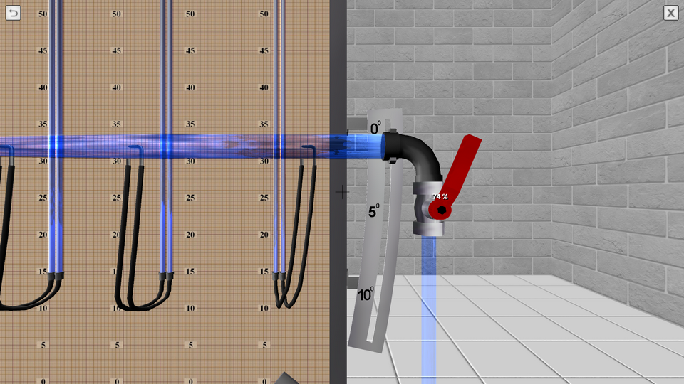
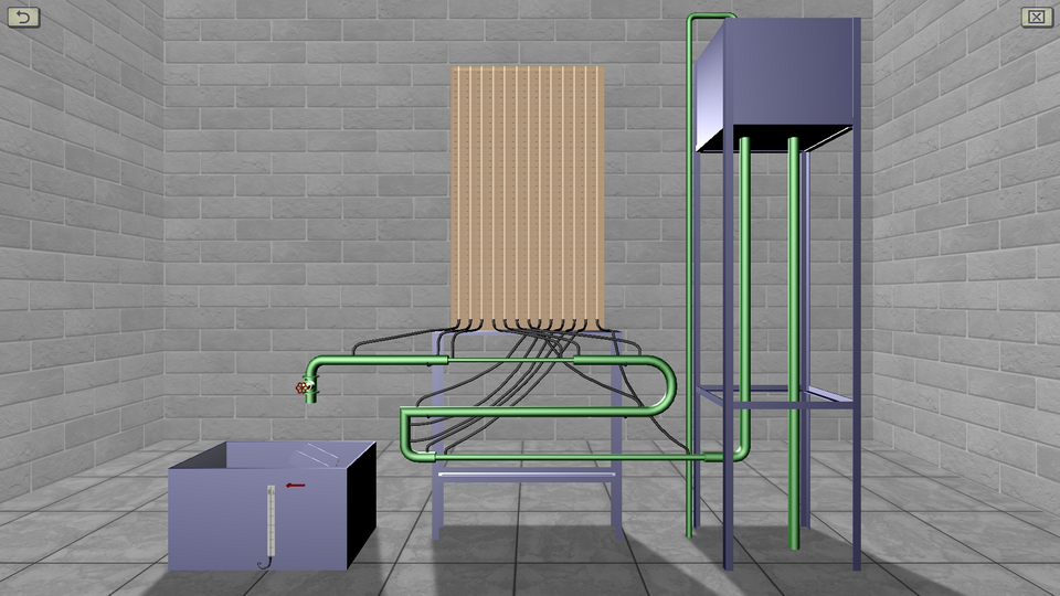
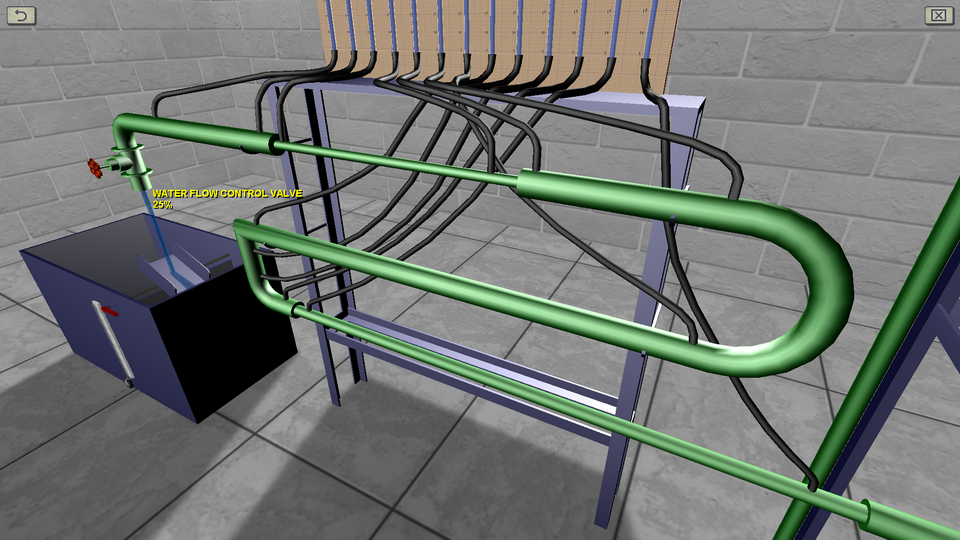
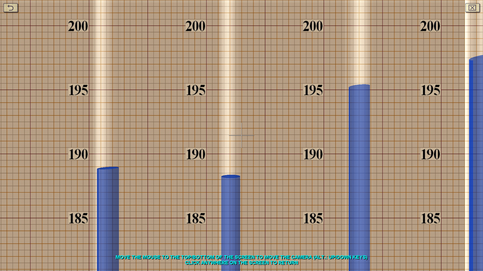
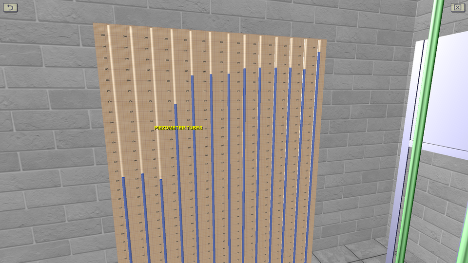
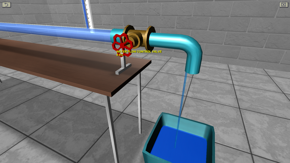
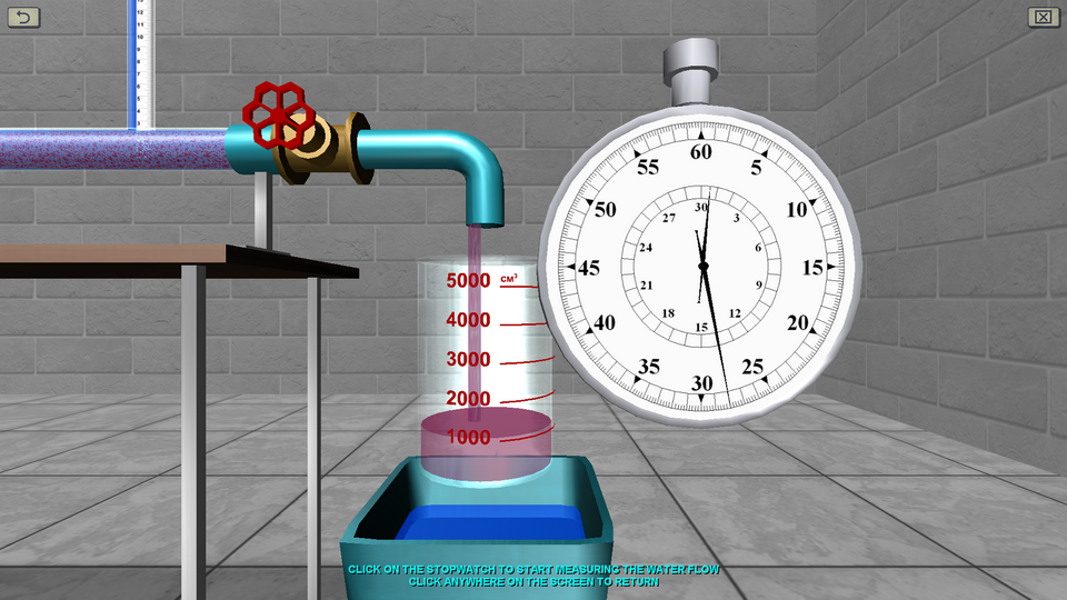
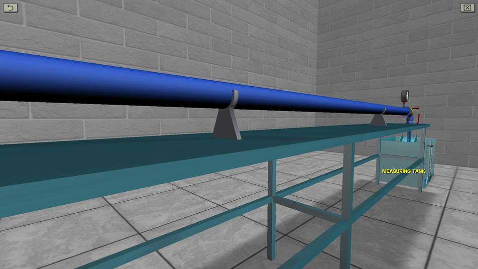
5. The Study of Hydraulic Resistance of Pressure Pipe
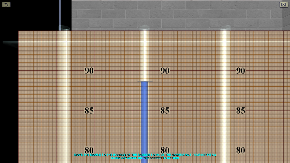
OBJECTIVE: The determination from experimental data of the value of the hydraulic friction coefficient and the value of the local resistance coefficient for three types of local resistances; the establishment of areas of hydraulic resistance, in which the sections of the pressure pipeline worked; the calculating the values of hydraulic friction coefficients according to the corresponding empirical formulas; the finding reference values of local resistance coefficients; the evaluation of the convergence of the experimental coefficients of hydraulic friction and local resistance with their calculated (reference) values; the plotting a pressure chart according to the experimental data. SUMMARY: The study of hydraulic resistance is one of the main topics of the course in theoretical hydromechanics. The laboratory stand consists of a combined pipeline simulating various connections, a stand with measuring piezometers, a water tower and a flow meter tank. Water flow in the system is measured using a stopwatch.
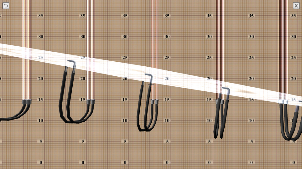
6. The Study of the Laminar and Turbulent Flow of Fluid
OBJECTIVE: The experimentally confirmation the existence of laminar and turbulent flow of fluid by observing the process of staining a stream of water in a glass tube; the calculation according to the experiments of the Reynolds number values in the laminar and turbulent regimes, comparing them with the critical one; the plotting, according to the experimental data, a graph of the pressure loss along the length of the mean flow velocity, determining with its help the critical velocity and the critical Reynolds number; the confirmation (using the plotted graph) of the proportionality of head loss along the length of the average flow velocity to the first degree in the laminar mode, and in the case of turbulence – to the extent of 1.75≤m≤2. SUMMARY: The laboratory stand consists of a pressure tank, a horizontal glass tube, two measuring piezometers and a flow meter tank. A trickle of colored liquid is fed into the glass tube, allowing you to visually observe the flow pattern. To change the water flow in the system, there is a control valve installed at the end of the pipeline. Water flow in the system is measured using a stopwatch.
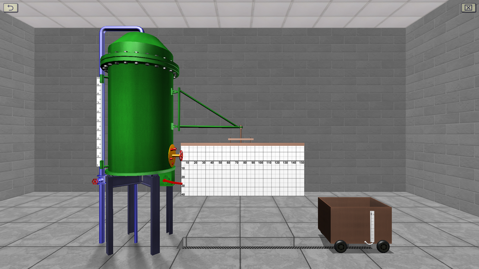
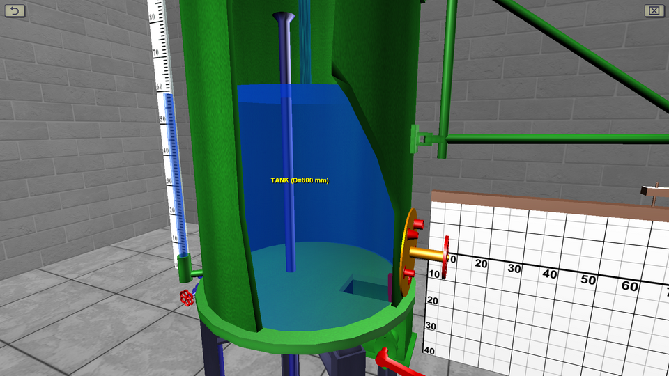
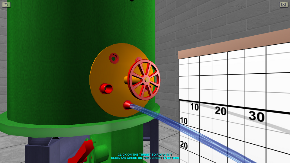
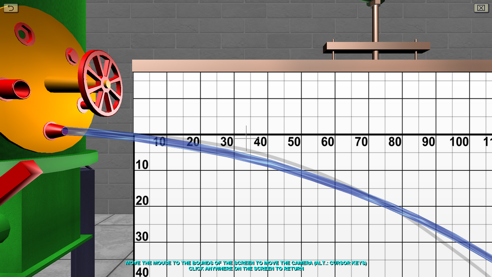
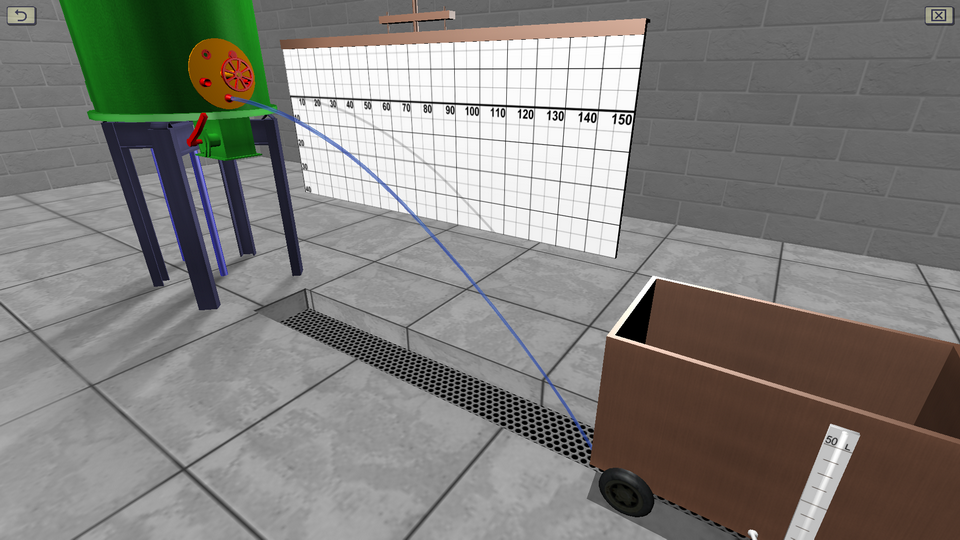
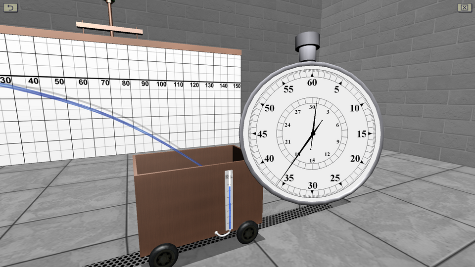
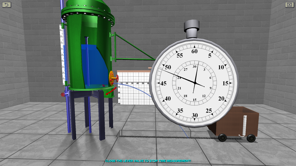
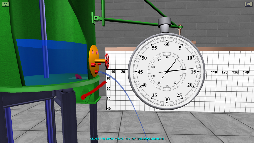
7. The Study of Fluid Flow through Small Holes in a Thin Wall and Nozzles
OBJECTIVE: The determination according to experimental data of the coefficients: hole flow rate and velocity, jet compression and hole resistance when water flows through a small round hole 2 cm in diameter at a constant pressure to the atmosphere; the determination of the coefficient of discharge of the nozzle and the resistance of the nozzle for the external cylindrical and conical (converging and diverging) nozzles with constant pressure into the atmosphere; the comparison of the values of the coefficients obtained in the experiments, with the reference and the calculation of relative deviations. SUMMARY: The laboratory stand consists of a cylindrical tank equipped with a water level indicator, a rotating turret and a lever valve. The shape of the flowing stream of water is controlled using a plane coord grid. To measure the flow, a mobile tank and a stopwatch are used.
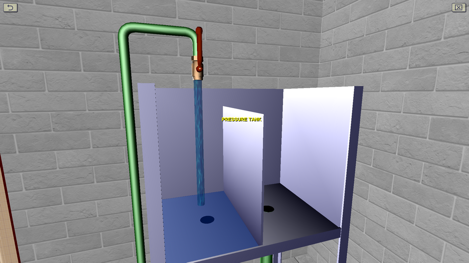
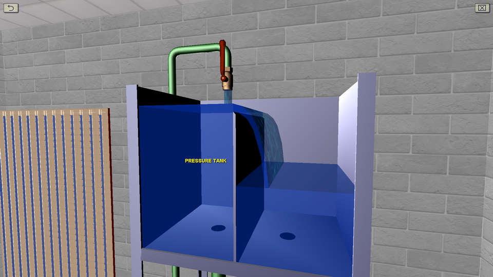
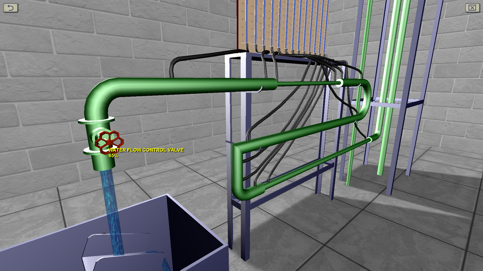
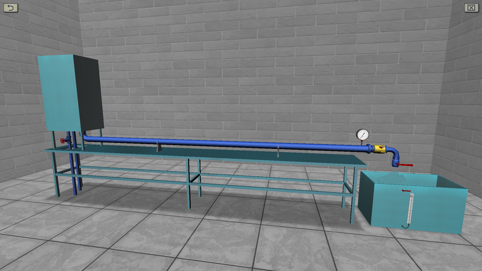
8. The Study of the Direct Water Hammer in Pressure Pipe
OBJECTIVE: The experimentally determination the magnitude of the pressure increase in a direct hydraulic hammer in the pressure pipeline; the compartion it with a theoretical value; the calculation of relative deviation. SUMMARY: The laboratory stand is equipped with a pressure tank, a flow tank and a long metal pipe. At the end of the pipeline break valve is installed and the water flow control valve. Water flow in the system is measured using a stopwatch.
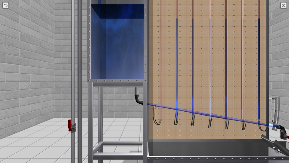
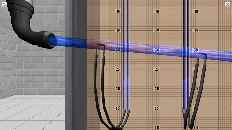
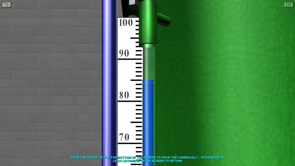
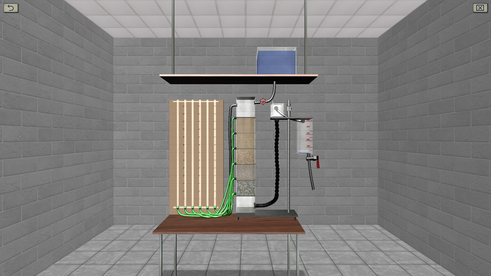
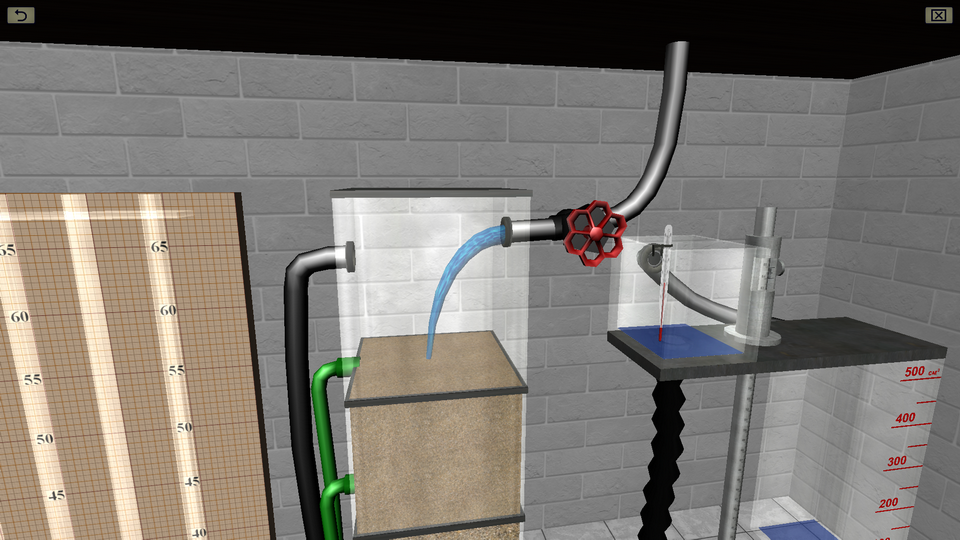
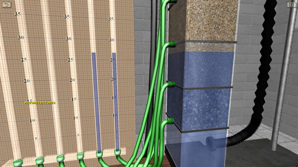
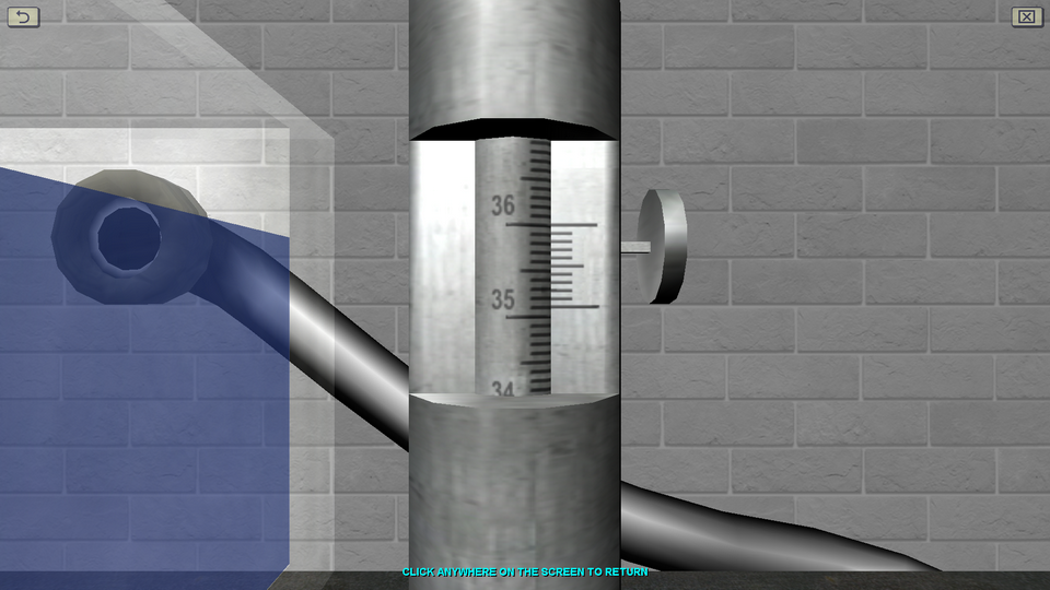
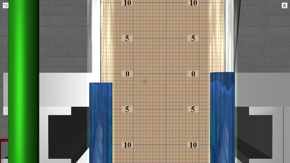
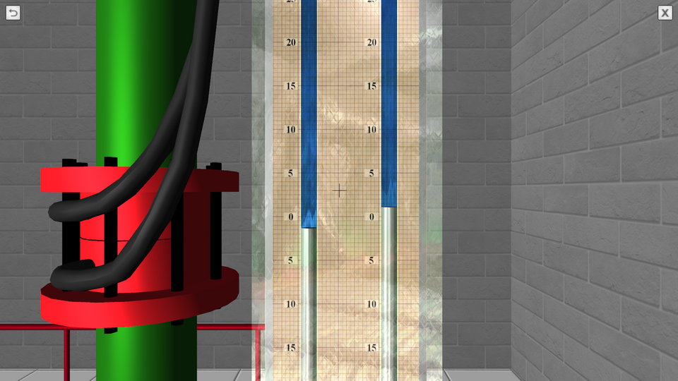
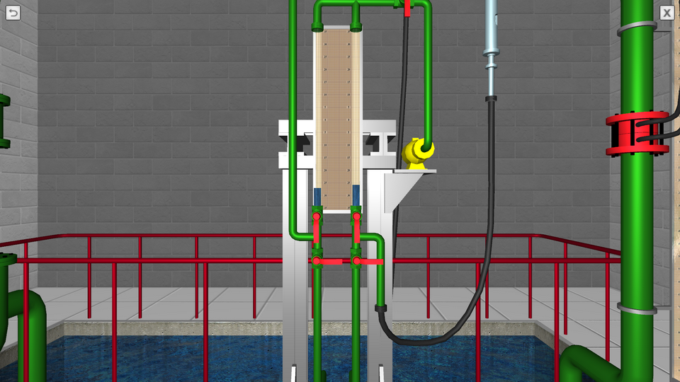
9. The Study of Filtration in Sandy Soil at Darcy Device
OBJECTIVE: The confirmation the validity of the Darcy law by constructing to scale graphs of the filtration rate versus pressure gradient (graphs for five types of sandy soil, differing in particle size); the determination of the average value of the filtration coefficient for one type of sandy soil according to the plot, with its indication on the graph; the plotting (on a scale) according to a single experiment a pressure profile (head pressure variation along the filtration path). SUMMARY: The laboratory stand is represented by a vertical glass column having several sections with soil of various grain sizes. The water is fed from the top down into the column. At each level of the column, a measuring piezometer is connected using a flexible hose. Water pressure is regulated using a special overflow device. Water flow in the system is measured using a stopwatch.
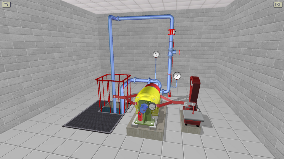
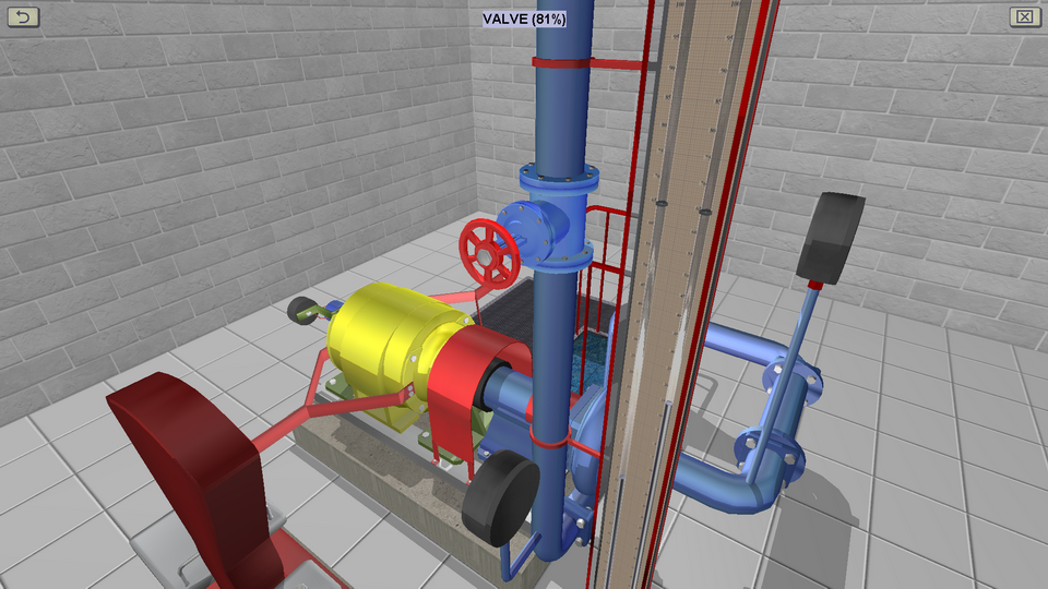
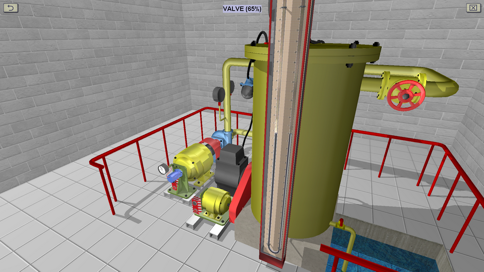
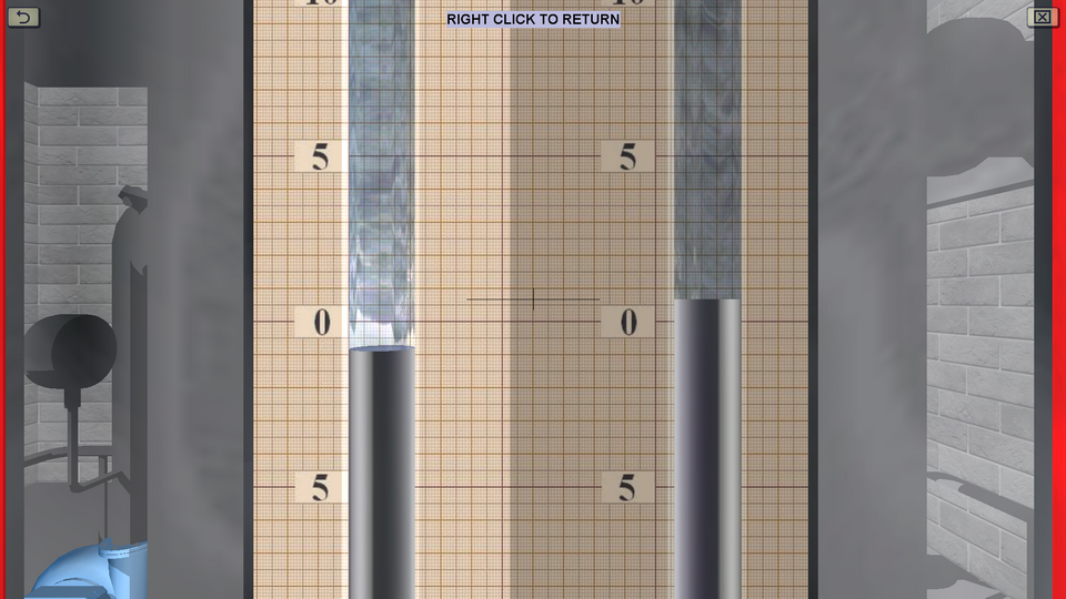
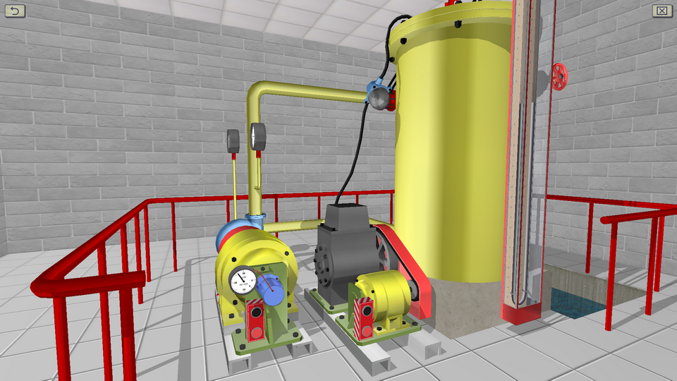
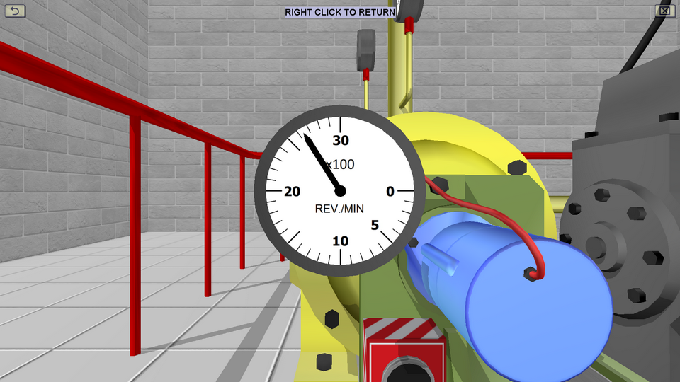
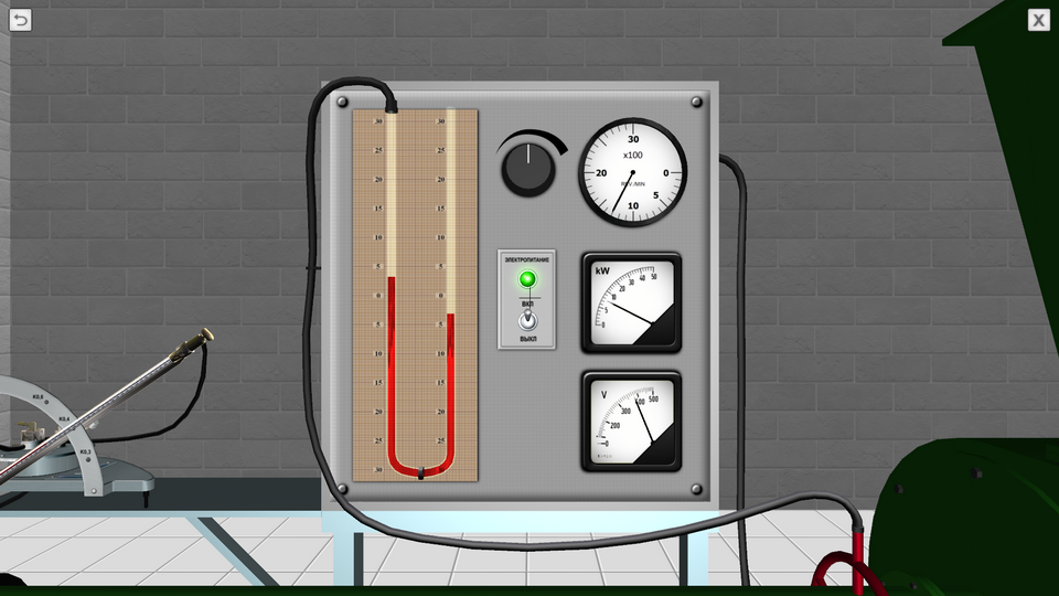
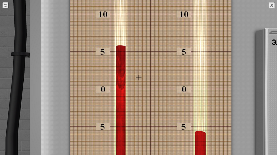
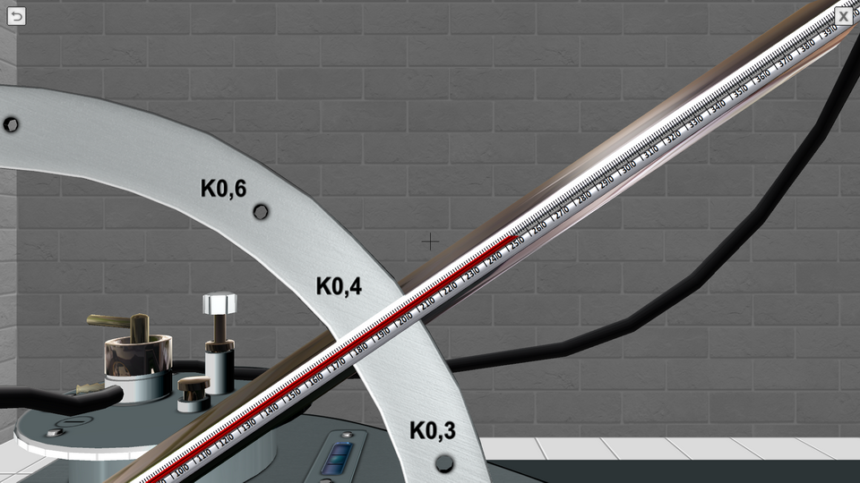
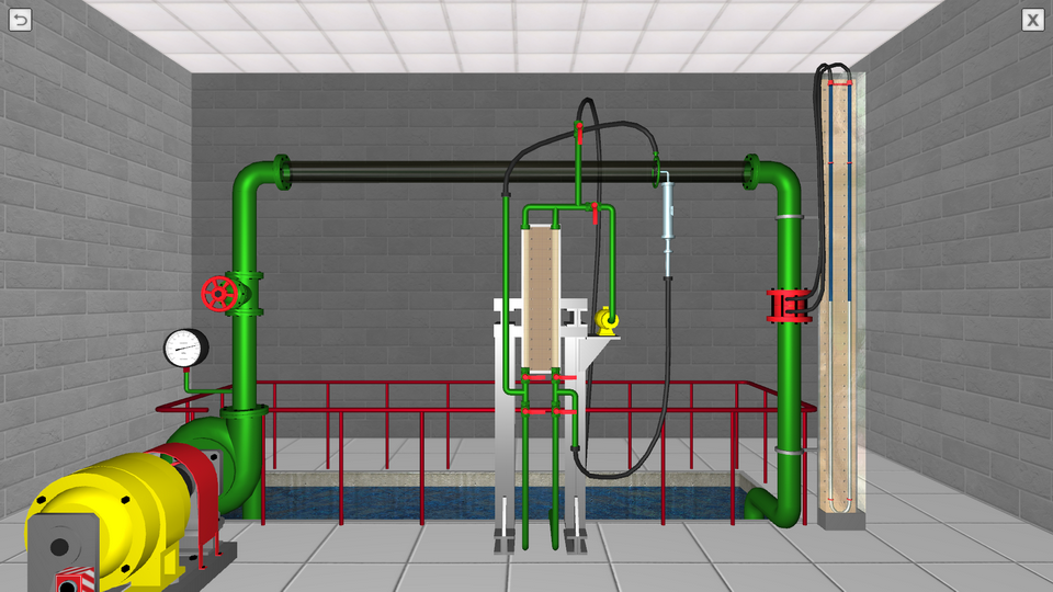
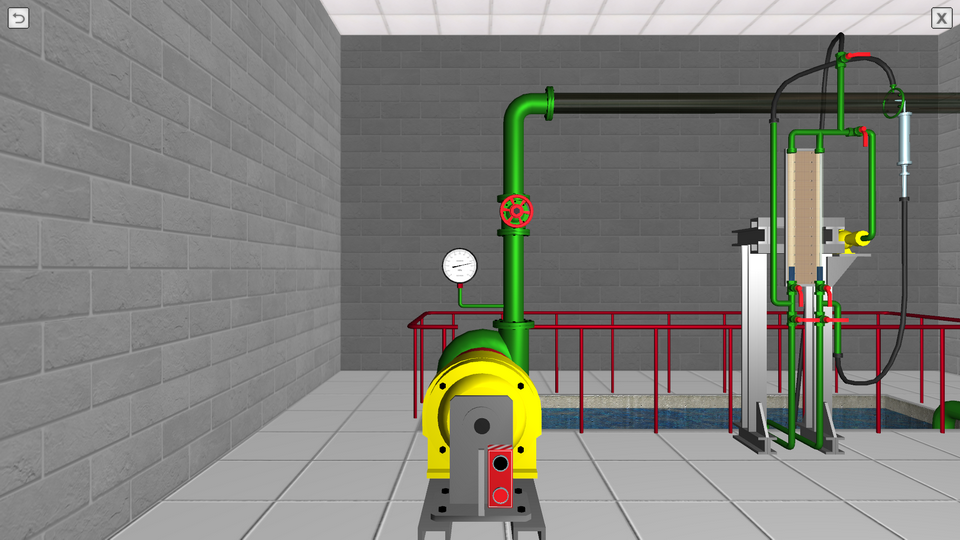
10. The Parametric Tests of Centrifugal Pump
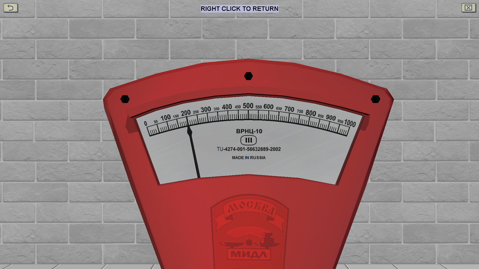
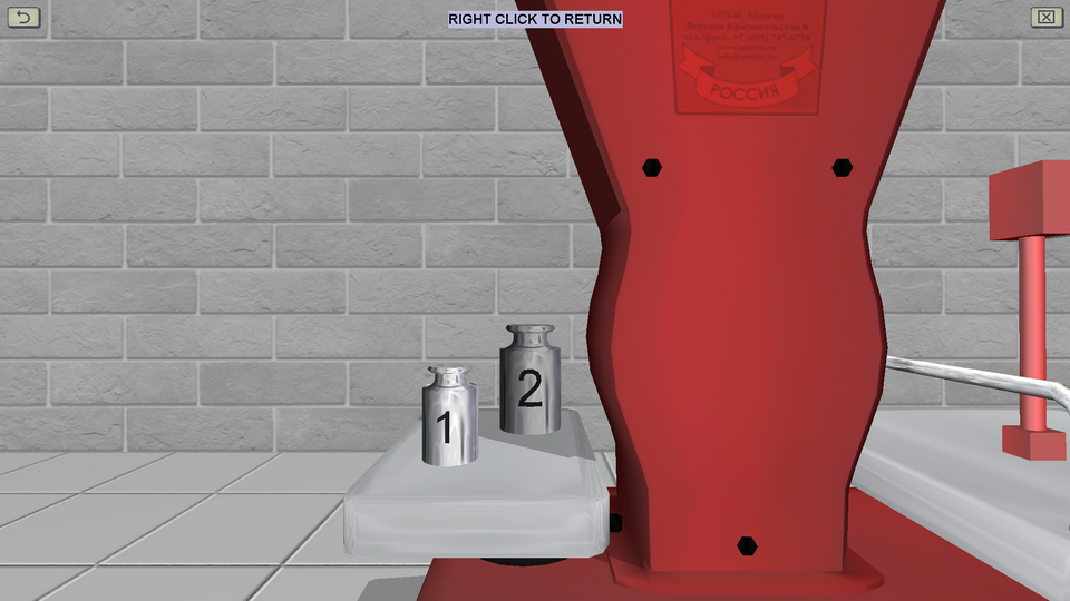
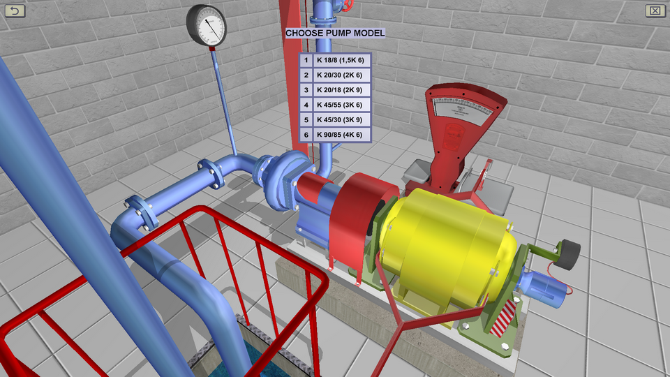
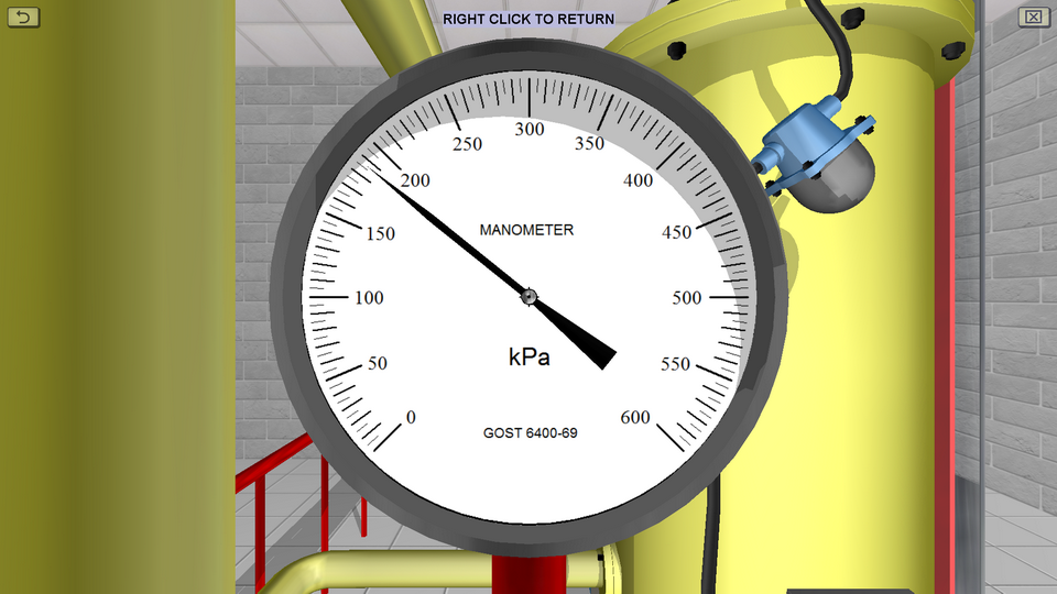
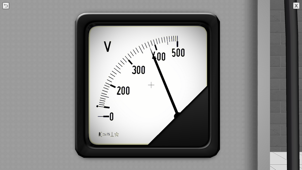
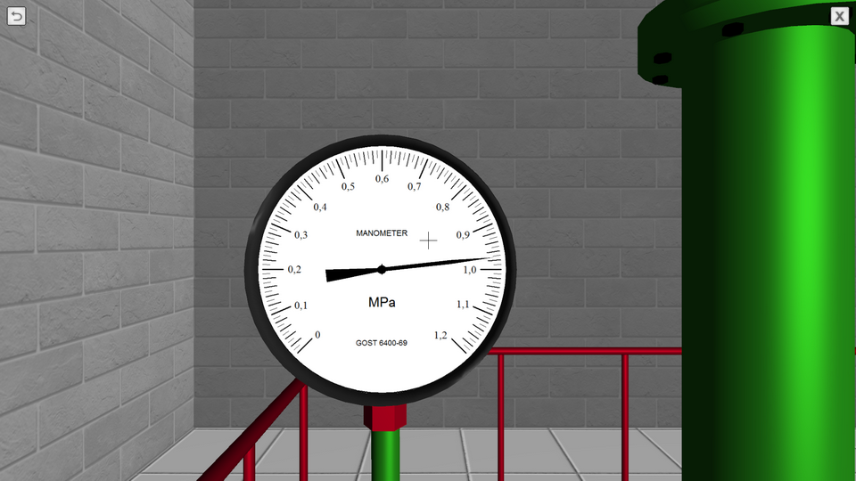
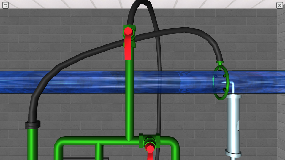
OBJECTIVE: The installation of at least 8-10 different pump operation modes using a gate valve, the opening of which varies from 0 to 100%; the measurement of instrument readings (pressure gauge, vacuum gauge, balance, tachometer and differential pressure gauge) at each mode; the calculation of the parameters to build the pressure and energy characteristics of the pump. SUMMARY: The main element of the laboratory stand is a centrifugal pump with an electric motor. Brand of the pump gets out in the course of work. With the help of a piping system in the installation water is circulated. In the course of work, pressure, water flow, shaft rotational speed and torque of the pump electric motor are measured. To measure the flow of water using a measuring diaphragm and a U-shaped mercury differential pressure gauge.
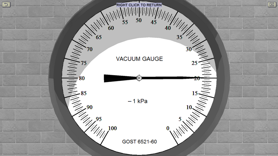
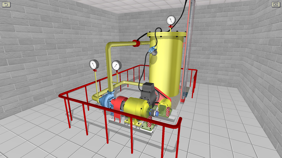
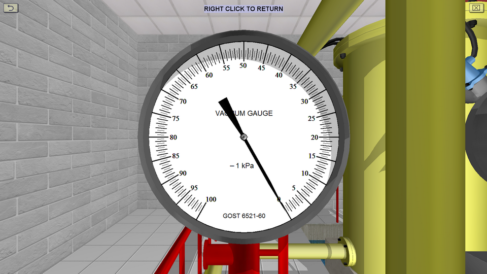
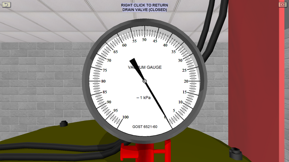
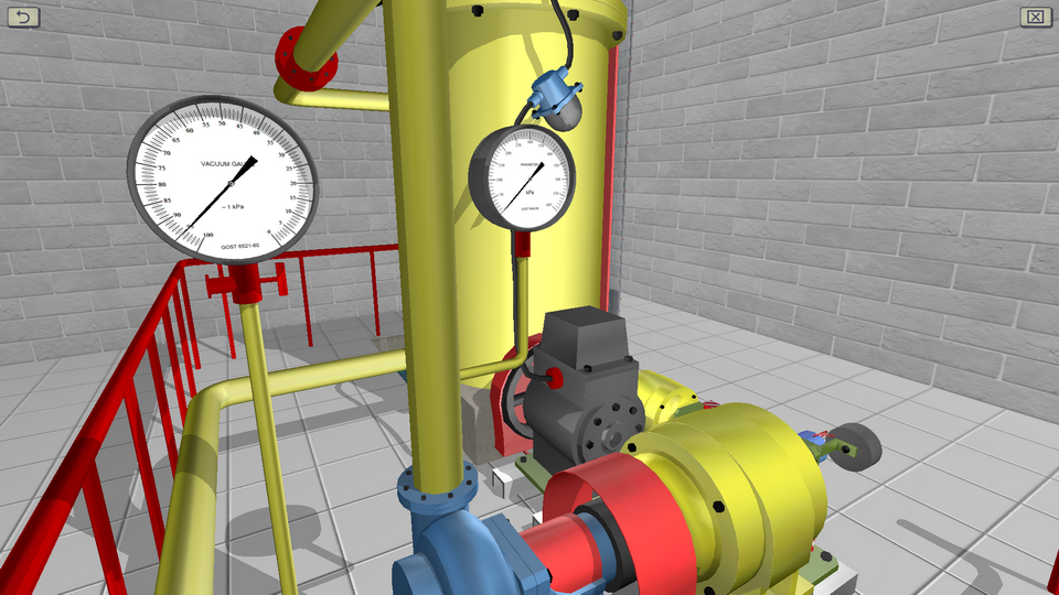
11. The Cavitation Tests of Centrifugal Pump
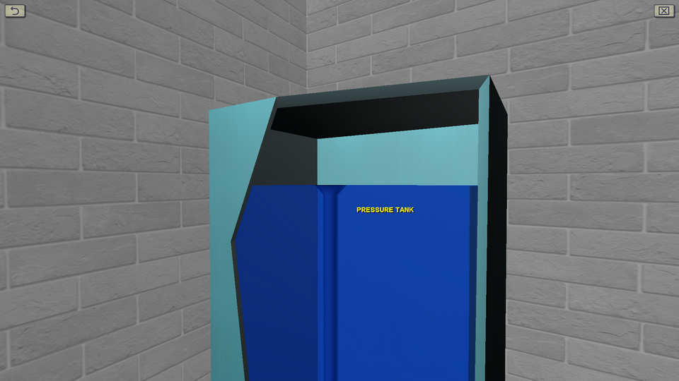
OBJECTIVE: The setup of at least three different modes of pump operation using a valve, the opening of which varies from 0 to 100%; the measurement of instrument readings (pressure gauge, vacuum gauge, tachometer and differential pressure gauge) each time the valve is opened (by sequentially setting the vacuum pressure on the surface of the tank from 0 to 95 kPa); the calculation of the parameters necessary for the construction of the private cavitation and cavitation characteristics of the pump. SUMMARY: The laboratory stand includes a centrifugal pump, a vacuum gauge pump, a sealed tank, a piping system and measuring instruments. Water pressure is measured using spring pressure gauges. Vacuum pressure is measured by means of a vacuum gauge equipped with a pressure relief valve. To measure the flow of water using a measuring diaphragm and a U-shaped mercury differential pressure gauge.
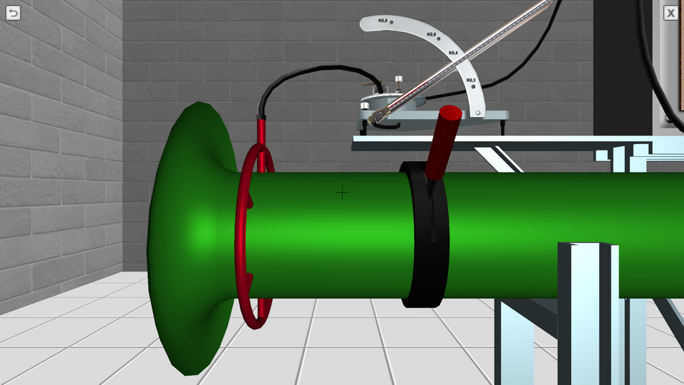
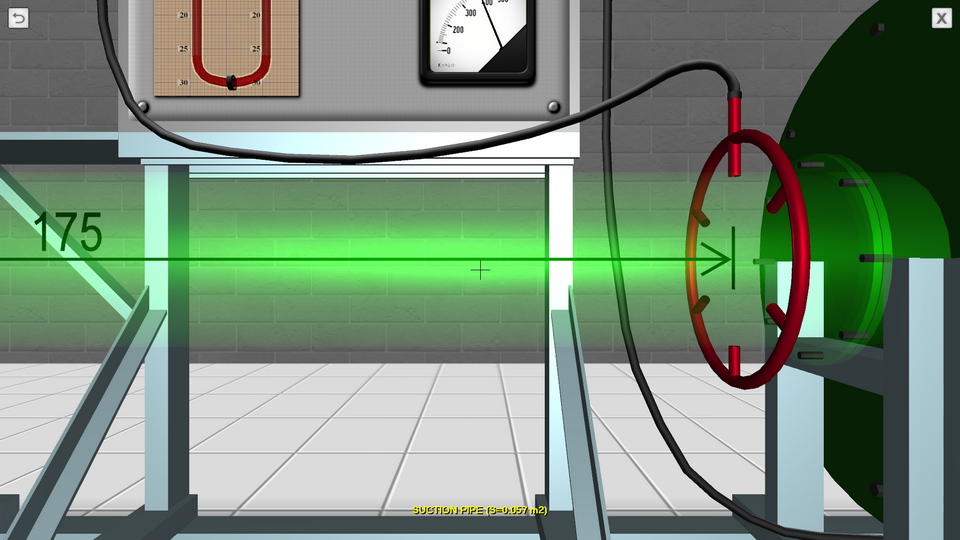
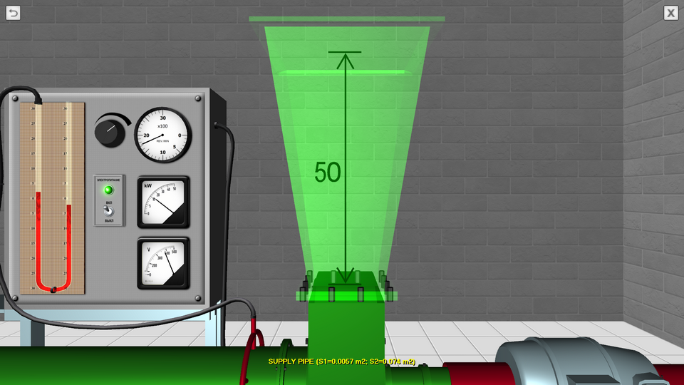
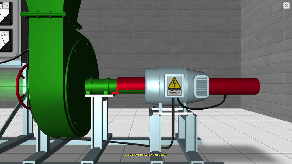
12. The Study of Centrifugal Fan Characteristics
OBJECTIVE: The study the physical process of the passage of air through the manifold under the pressure created by the centrifugal fan and the construction of the main characteristics of the centrifugal fan according to experimental data. SUMMARY: A virtual laboratory stand allows for interactive user participation in the implementation of basic laboratory work of theoretical hydromechanics course. In the process of performing laboratory work, the user makes measurements of the main experimental parameters – airflow pressure in two cross-sections of the suction pipe and in one cross-section of the discharge pipeline, and also reads the tachometer and wattmeter installed on a special measuring board.
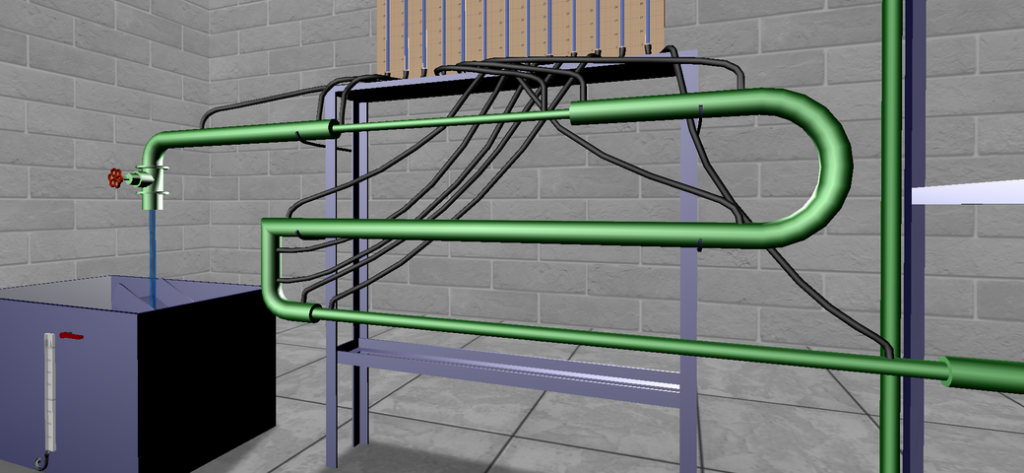
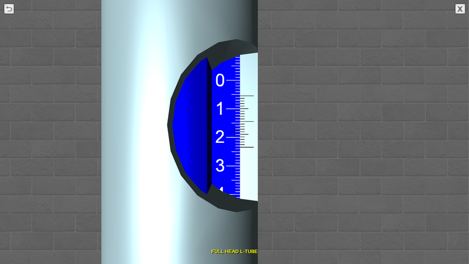
13. The Determination of Velocity in the Cross Section of a Round Pipe
OBJECTIVE: The measuring the flow rate of a fluid in a cross-section of a circular pipe using an angled full-pressure tube. SUMMARY: The methods of measuring water velocity considered in the laboratory work are used in technical systems operating according to the laws of theoretical hydromechanics. The laboratory stand includes a centrifugal pump, a system of pipelines and measuring devices. The investigated section of the pipeline has a glass insert, in the cross section of which the measuring diaphragm and measuring tube Pitot are installed. Thus, the selection of pressure on the pipe wall for measuring the piezometric head is made through the holes at several points of the wall perimeter, combined by an equalizing collector, from which pressure is supplied to the measuring device. To change the parameters of the installation, adjustment valves are provided. To measure the flow of water using a measuring diaphragm and a U-shaped mercury differential pressure gauge.